
DCFR Insight 23 / Cooling + Water + AI Infrastructure
Capacity DeliveryData Center Cooling Systems: Air, Direct-to-Chip, and Immersion Cooling
Cooling now determines rack density, water exposure, energy use, site acreage, operating cost, and even whether an AI data center site is viable. A practical comparison of air cooling, rear-door heat exchangers, direct-to-chip liquid cooling, immersion, warm-water systems, and the technologies coming next.
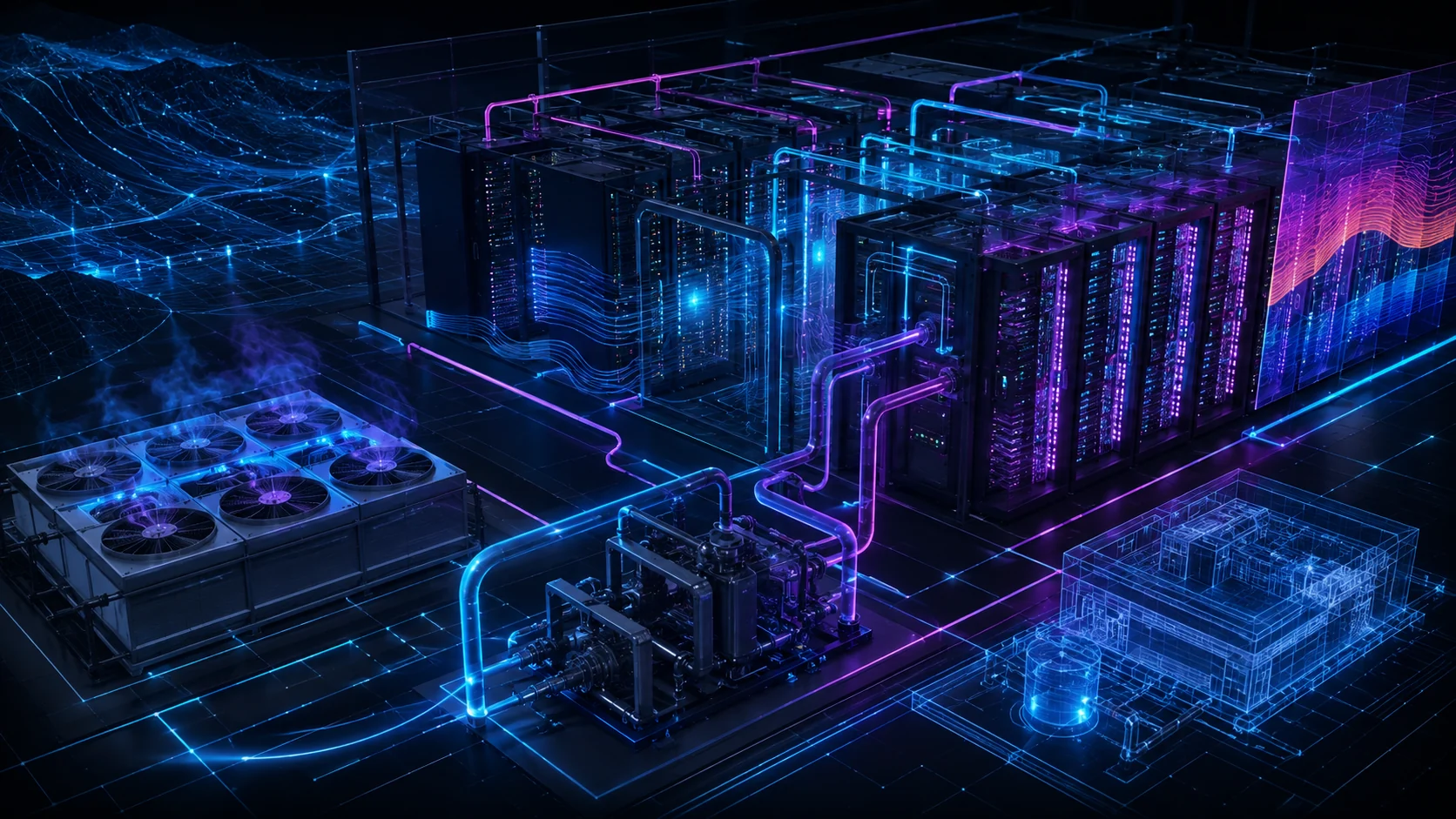
Cooling is now a site-selection and capacity-delivery decision
Data center cooling can no longer be treated as a downstream mechanical selection. AI accelerators have concentrated far more heat into each rack, while water constraints, utility prices, noise limits, equipment lead times, and campus phasing increasingly determine what can actually be delivered. The useful question is not which cooling technology wins in isolation. It is whether the complete thermal chain can capture heat at the chip, transport it through the rack and building, reject or reuse it under design-weather conditions, survive credible failures, and remain maintainable throughout the owner’s operating model. A concept that performs efficiently at nominal load may still be unsuitable if it consumes unavailable water, requires unsupported IT hardware, expands the equipment yard beyond the parcel, or cannot maintain temperatures during a utility or component event. DCFR therefore evaluates cooling as a coupled land, power, water, building, controls, acoustics, resilience, and operations problem.
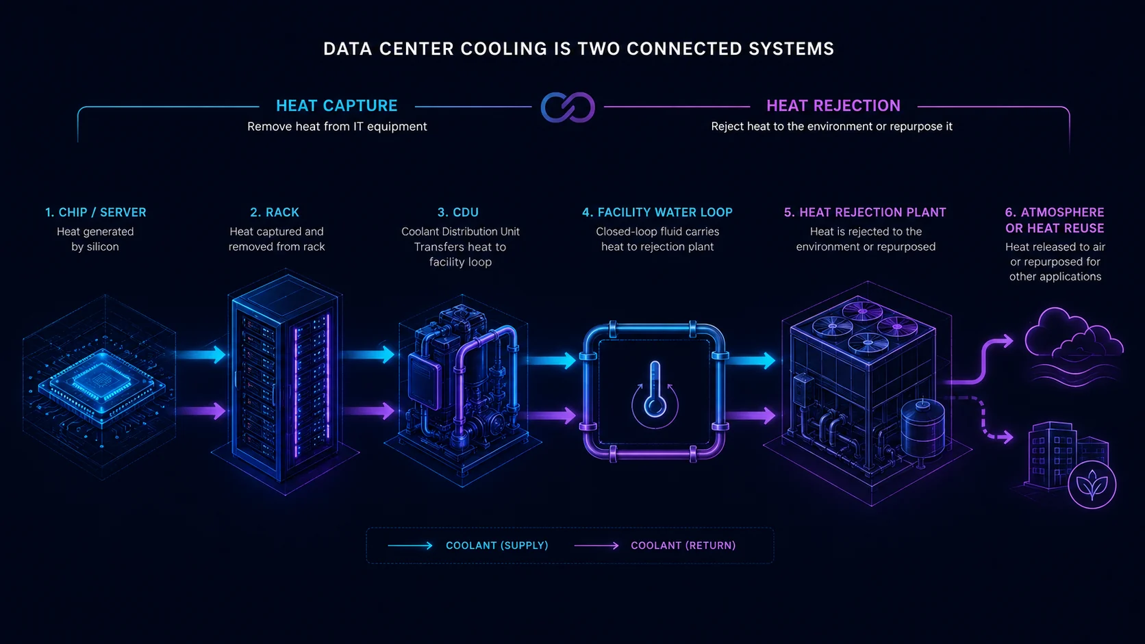
Start with workload, rack density, and the complete thermal chain
The design basis should define current and future rack power, diversity, utilization, heat-load ramp, supply-temperature requirements, allowable inlet conditions, liquid-cooling readiness, and the fraction of heat that must still be removed by air. A nominal megawatt target does not reveal whether the hall contains many moderate-density racks or a smaller number of extreme-density AI clusters. The team must also establish liquid quality, materials compatibility, pressure boundaries, leak detection, isolation, flushing, water treatment, controls, redundancy, maintenance bypasses, and responsibility at every handoff between the IT equipment, technology cooling system, coolant distribution unit, facility water system, and heat-rejection plant. Published equipment performance is only a starting point; final temperatures, flows, pressure drops, approach temperatures, part-load behavior, and failure sequences require project-specific MEP engineering and equipment-vendor confirmation.
Layer 1 — IT / Rack Heat-Capture Technologies
| Technology | Typical role | Density suitability | Key advantage | Primary constraint | 2026 DCFR view |
|---|---|---|---|---|---|
| Conventional air cooling | Moves heat from IT equipment into room air | Low–Medium | Mature, familiar, broadly serviceable | Airflow volume, fan energy, recirculation, and space become limiting as rack density rises | Economically sound where rack density remains modest and airflow can be controlled effectively |
| Rear-door heat exchanger | Captures rack exhaust heat at the rear of the enclosure | Medium–High | Raises usable rack density while retaining conventional air-cooled servers | Introduces rack-level liquid connections, door weight, hose routing, isolation, and maintenance interfaces | Strong retrofit and transition strategy |
| Single-phase direct-to-chip cold plates | Captures heat directly from CPUs, GPUs, memory, or other high-heat components | High–Extreme | High liquid heat-capture efficiency and strong support for current AI platforms | Residual air load, coolant quality, CDUs, connectors, leak management, vendor compatibility, and service procedures | Leading current solution for new high-density AI deployments where the IT platform supports liquid cooling |
| Single-phase immersion | Submerges qualified IT equipment in dielectric liquid | Extreme | Exceptional heat transfer and elimination or reduction of server fan energy | Specialized hardware handling, fluid management, warranties, maintenance procedures, and vendor ecosystem | Powerful specialized solution rather than a universal default |
| Two-phase direct-to-chip | Uses phase change at or near the processor cold plate to absorb very high heat flux | Extreme+ | Potentially very high heat-flux capability with reduced pumping demand | Commercial maturity, refrigerant/fluid selection, pressure control, seals, servicing, qualification, and vendor ecosystem | Important emerging next-generation technology; validate delivery-date maturity |
| Two-phase immersion | Uses boiling dielectric fluid and condensation to remove heat from immersed electronics | Extreme+ | Exceptional theoretical heat-transfer capability | Fluid management, containment, environmental issues, service model, component qualification, and commercial maturity | Emerging / specialized; do not assume bankability without detailed vendor validation |
Layer 2 — Facility Heat-Rejection Technologies
| Technology | Water profile | Energy profile | Climate sensitivity | Land / acoustic implication | 2026 DCFR view |
|---|---|---|---|---|---|
| Dry cooler / fluid cooler | Very low to zero routine cooling-water consumption | Good when facility-water temperature and climate permit high economizer hours | High | May require larger coil area, fan capacity, and acoustic control at high ambient temperatures | Strong option for water-constrained sites and warm-water liquid systems |
| Adiabatic dry cooler | Low; water used primarily during hotter conditions | Can reduce peak fan or mechanical cooling demand | Moderate–High | Similar to dry cooling with additional water treatment and operating modes | Useful hybrid strategy where limited water use is acceptable |
| Open cooling tower | High relative to dry systems | Thermodynamically strong heat rejection in suitable conditions | Moderate | Requires tower area, drift management, plume consideration, treatment, blowdown, makeup water, and acoustic review | Potentially efficient but water availability and local water stress must be explicitly evaluated |
| Air-cooled chiller | Low | Higher compressor energy when mechanical cooling operates | Moderate–High | Exterior plant footprint and fan/compressor noise | Useful where water reduction is important but low coolant temperature must be maintained |
| Water-cooled chiller + cooling tower | Medium–High | Can provide strong mechanical efficiency | Moderate | Requires cooling tower, chiller plant, pumps, treatment, and water infrastructure | Mature solution where water availability and lifecycle economics justify complexity |
| Hybrid dry + adiabatic + mechanical trim | Low–Variable | Potentially excellent when controls maximize dry operation and use assist only when necessary | Adaptable | More equipment and control complexity but flexible across operating conditions | One of the strongest architectures for many high-density AI campuses |
| Heat-reuse / district-energy connection | Project specific | Can convert rejected heat into useful energy but may require heat pumps | Low–Moderate | Requires real adjacent heat demand, piping routes, interfaces, and commercial agreements | Valuable only where technically and commercially usable heat demand actually exists |
Heat-Capture Technology Decision Matrix
| Heat-capture technology | Rack-density fit | Thermal efficiency potential | Site water implication | CapEx | O&M complexity | Retrofit fit | AI / HPC readiness | DCFR planning view |
|---|---|---|---|---|---|---|---|---|
| Conventional air | Low–Medium | Moderate | Depends on facility heat-rejection architecture | Low | Low | Excellent | Limited | Economically sound where rack density remains modest. |
| Rear-door heat exchanger | Medium–High | Good | Heat-rejection dependent | Moderate | Moderate | Excellent | Good | Strong retrofit and transition strategy. |
| Single-phase direct-to-chip | High–Extreme | Excellent; total-system performance depends on facility architecture | Heat-rejection dependent; can approach zero cooling-water use with dry rejection | Moderate–High | Moderate | Moderate | Excellent | Leading current choice for new high-density AI where the IT platform supports liquid cooling |
| Single-phase immersion | Extreme | Excellent | Heat-rejection dependent; immersion itself does not determine site WUE | High | High / specialized | Poor | Excellent thermally | Thermally powerful specialized solution; validate hardware compatibility, maintenance model, fluid ecosystem, warranties, and vendor support |
| Two-phase direct-to-chip | Extreme+ | Potentially exceptional; total-system performance depends on facility architecture | Heat-rejection dependent; can approach zero cooling-water use with dry rejection | Emerging | Emerging | Limited | Next-generation | Important emerging technology; validate commercial maturity and vendor support. |
| Two-phase immersion | Extreme+ | Potentially exceptional | Heat-rejection dependent; immersion itself does not determine site WUE | Emerging / specialized | High / specialized | Poor | Next-generation | Emerging specialized option; validate fluid, qualification, service model, environmental requirements, and vendor maturity. |
Heat capture and heat rejection must be evaluated separately. A direct-to-chip or immersion system can still use significant site water if connected to evaporative heat rejection, while the same IT cooling approach may use near-zero cooling water when paired with appropriately designed dry heat rejection.
No cooling technology is universally optimal. DCFR evaluates viable cooling architectures against the site's rack density, climate, water availability, electrical cost, land availability, noise sensitivity, redundancy strategy, phasing, maintenance model, and IT-platform compatibility.
Air cooling still works—within a defined density envelope
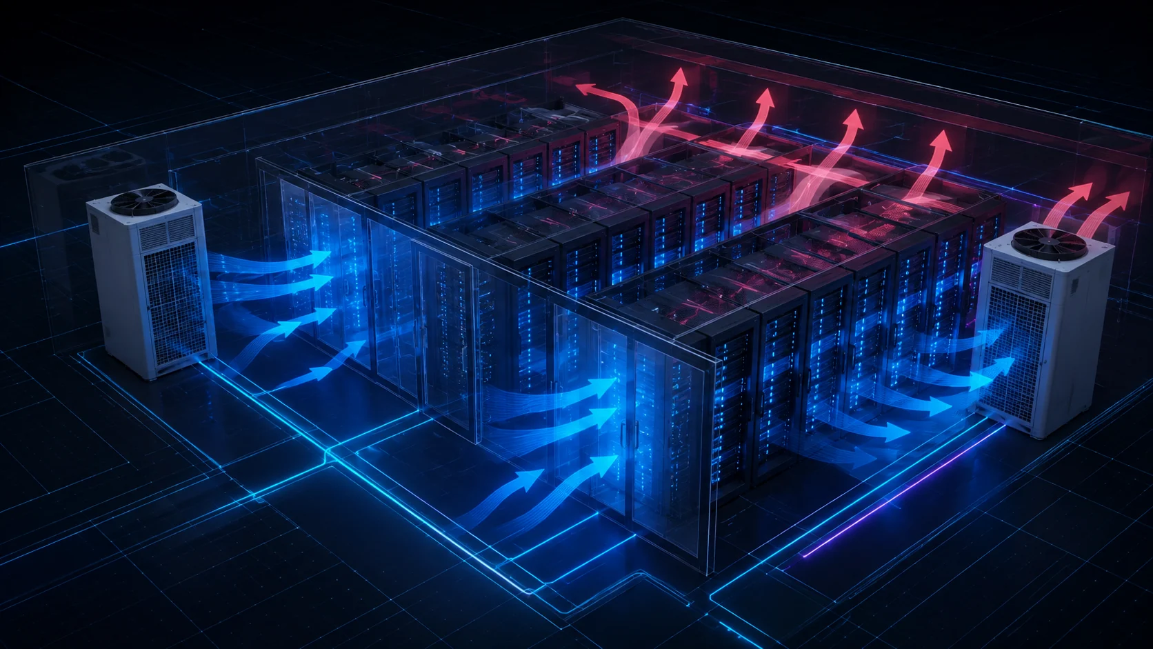
Conventional CRAC or DX systems remain simple and economical for modest loads, edge facilities, legacy rooms, and sites where first cost and familiar maintenance dominate. CRAH units connected to chilled water provide more plant flexibility and can serve substantial campuses, especially when containment, blanking panels, cable management, raised-floor pressure, fan control, and supply-air reset are disciplined. Outside-air economization can reduce compressor hours in suitable climates, while evaporative or adiabatic assistance can lower fan and compressor energy at the cost of water use, treatment, plume or drift considerations, and more operating modes. Air is less capable than liquid at transporting concentrated heat; increasing airflow eventually increases fan energy, duct and plenum area, noise, recirculation sensitivity, and stranded white space. Air cooling is therefore not obsolete, but its practical rack-density limit must be validated rather than assumed.
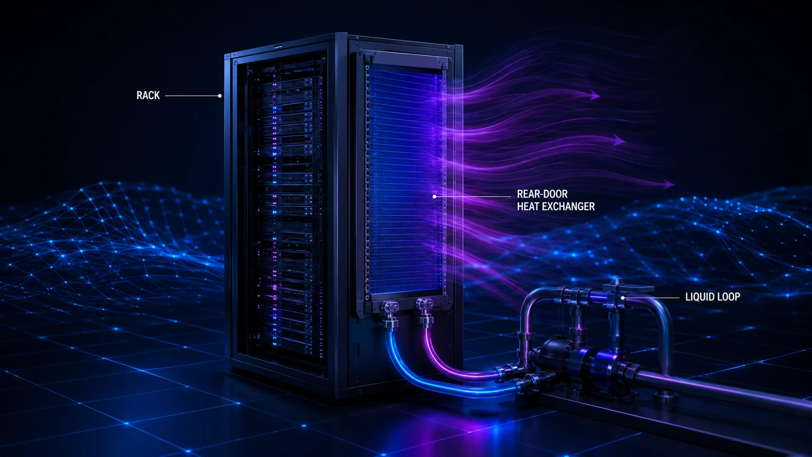
Rear-door heat exchangers provide a practical transition
An active or passive rear-door heat exchanger intercepts hot rack exhaust and transfers much of that heat to a liquid loop before it enters the room. This can raise usable rack density, reduce recirculation, and preserve familiar air-cooled servers and service practices. It is particularly attractive in retrofits where rebuilding the entire data hall or replacing the IT fleet is unrealistic. The design must account for door weight and swing, hose and manifold routing, condensate risk, water temperature, rack fan interaction, pressure drop, leak detection, isolation, access, and the remaining room-cooling load. Rear-door systems do not eliminate the facility thermal chain; they relocate heat capture closer to the rack and introduce water connections at every served enclosure. Their value is strongest when those interfaces and the owner’s maintenance procedures are deliberately planned.
Direct-to-chip is the leading current path for high-density AI
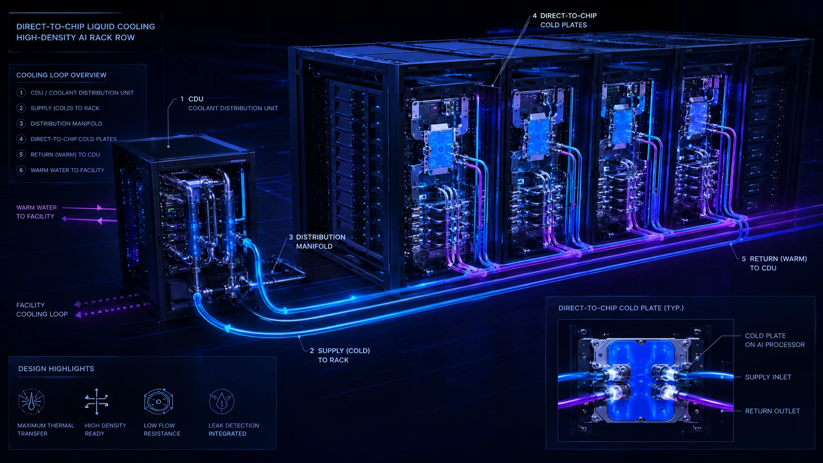
Direct-to-chip systems place cold plates on CPUs, GPUs, memory, or other high-heat components and circulate coolant through rack manifolds to a CDU. Because liquid carries heat more effectively than air, the approach can support high and extreme rack densities with lower fan energy and higher coolant temperatures. It also fits the direction of many current AI server platforms. However, direct-to-chip rarely captures every watt: power supplies, drives, networking, and other components may leave a meaningful residual air load. Designers must quantify the liquid capture ratio and provide air cooling for the balance. They must also coordinate coolant chemistry, filtration, materials, connectors, dripless couplings, pressure control, pumping, leak response, CDU redundancy, controls, and ownership of the boundary between IT and facility systems. Its strong efficiency potential does not make it universally optimal; platform compatibility and service capability remain decisive. Current rack-scale AI platforms demonstrate why this transition is already a delivery issue rather than a distant technology forecast. Commercial systems can now exceed 100 kW per rack, which materially changes the practicality of airflow-only heat removal, the residual room-cooling strategy, pipe distribution, CDU placement, floor and structural coordination, and heat-rejection capacity. This does not mean every AI deployment will operate at extreme rack density. It means feasibility studies should no longer assume yesterday’s rack power when testing tomorrow’s campus.
Immersion offers exceptional heat transfer with a different operating model
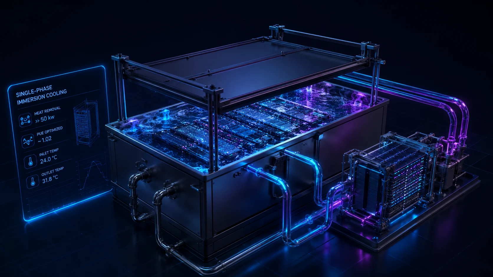
Single-phase immersion submerges qualified IT hardware in a dielectric fluid that remains liquid, then transfers heat through a secondary loop. It can achieve very high density, reduce server fan energy, and enable low-water heat rejection, but it changes rack form, lifting and service procedures, cabling, component qualification, fluid storage, spill response, filtration, fire strategy, warranties, and the supply chain for replacement parts. Two-phase immersion boils a dielectric fluid at the component surface and condenses the vapor, offering very high heat flux but adding fluid containment, environmental, pressure, material, and commercial-maturity considerations. The thermal performance can be compelling while the overall business case remains specialized. Owners should validate fluid availability, regulatory trajectory, vendor warranties, technician training, maintenance time, hardware refresh, and end-of-life handling rather than comparing only cooling energy.
Heat rejection determines energy, water, land, and noise
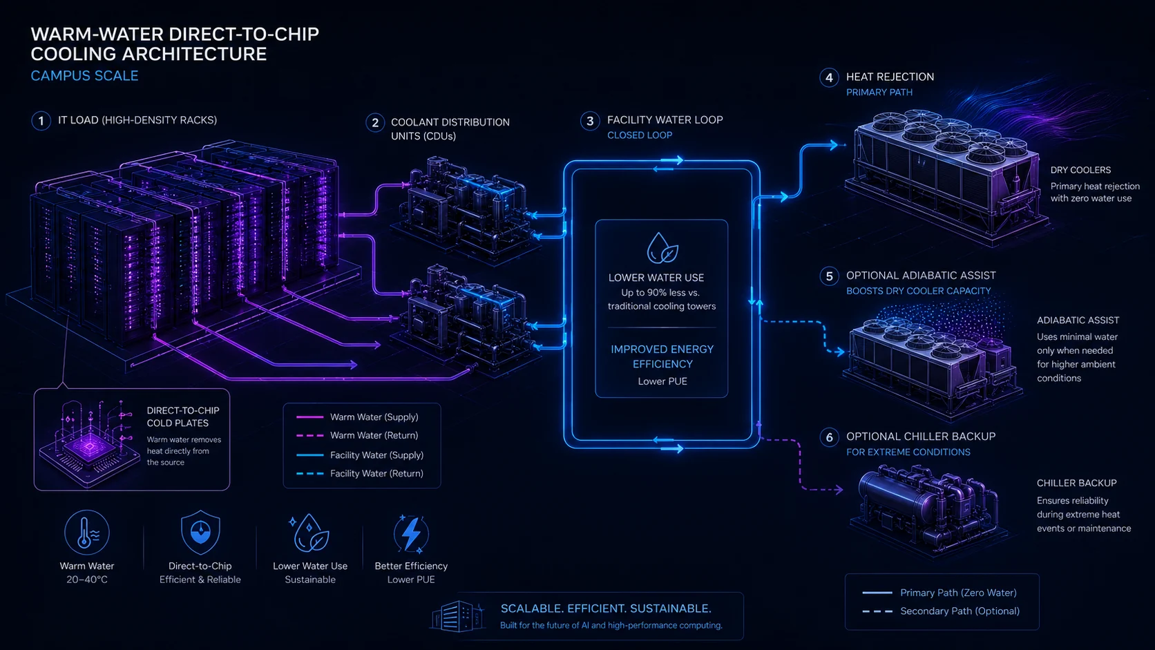
A liquid-cooled rack is not the end of the cooling system. Heat must still move to dry coolers, cooling towers, fluid coolers, chillers, evaporative systems, a district-energy connection, or a useful heat sink. Dry rejection can greatly reduce operational water demand but may require more coil area, fan power, site acreage, and acoustic mitigation, particularly at high ambient temperature. Evaporative rejection can improve thermodynamic performance and reduce equipment size while consuming water and requiring treatment, blowdown management, drift control, and a reliable water source. Chillers can preserve supply temperature during extreme weather but add compressor energy and refrigerant considerations. Planning must use appropriate hourly climate and design-weather data—not annual averages—and test normal, peak, degraded, maintenance, and water-curtailment conditions.
Warm-water architectures can unlock dry cooling and heat reuse
Higher coolant supply temperatures increase the number of hours when heat can be rejected without compressor operation. A warm-water direct-to-chip system may connect rack manifolds to CDUs, a closed facility water loop, and dry coolers, with adiabatic assistance or mechanical backup only when climate and resilience require it. This can reduce water exposure and improve energy performance, but the achievable temperature depends on the approved IT platform, cold-plate approach, liquid capture ratio, approach temperatures, fouling allowance, and design ambient conditions. Higher loop temperatures also make recovered heat more useful, although data-center waste heat is still often too low-grade for an economic customer without heat pumps. Heat reuse should be supported by a nearby, coincident, contractable demand; it should not be credited merely because a pipe connection is technically possible.
ASHRAE Liquid-Cooling Temperature Classes — Planning Context
| ASHRAE class | Maximum facility-water supply temperature | Planning implication |
|---|---|---|
| W17 | 17°C / 62.6°F | Relatively cool facility water; greater likelihood of mechanical cooling depending on climate and design |
| W27 | 27°C / 80.6°F | Greater economizer potential and reduced compressor dependence |
| W32 | 32°C / 89.6°F | Strong warm-water/free-cooling potential in many climates |
| W40 | 40°C / 104°F | Significant dry-cooling opportunity where approved IT equipment supports the temperature |
| W45 | 45°C / 113°F | High-temperature liquid architecture with stronger potential for compressor-free heat rejection and useful heat recovery |
| W+ | Above 45°C / 113°F | Emerging high-temperature cooling and heat-recovery territory |
ASHRAE W-class capability is not an instruction to operate every server at the class limit. The selected IT platform, cold plates, coolant, CDUs, approach temperatures, controls, reliability requirements, and vendor-approved operating envelope determine the actual project design temperature.
Efficiency is a system outcome, not a product label
Cooling efficiency must be evaluated across fans, pumps, CDUs, chillers, tower fans, water treatment, controls, and the effect of partial load and redundancy. PUE can help track facility overhead but can hide water impacts, local climate, IT utilization, and the energy embodied in external water or district systems. WUE likewise needs a clear boundary and should distinguish site water consumption from withdrawal and source stress. A low cooling-energy design may consume more water; a water-free concept may need more fan energy and land; an exceptionally dense solution may reduce building area while increasing operational specialization. Comparative modeling should use consistent loads, weather files, redundancy, setpoints, and boundaries, then test sensitivity to future rack mixes and utility rates. Claims of universal superiority usually indicate that a boundary or constraint has been omitted.
What DCFR would test on four different sites
Cooling feasibility should produce different answers for different parcels. DCFR should therefore test complete thermal architectures rather than applying one preferred technology everywhere. The following examples illustrate the type of planning logic that should occur before the mechanical basis of design is fixed.
Illustrative Site Cooling Scenarios
| Site condition | First architecture to evaluate | Why | Key confirmation |
|---|---|---|---|
| Cool / moderate climate + constrained water | High-temperature direct-to-chip + dry heat rejection | Long economizer periods may support low-water, low-compressor operation while maintaining high AI rack density | IT supply-temperature limits, design ambient conditions, dry-cooler area, fan power, acoustic impact, and peak-condition resilience |
| Hot / arid climate + severely constrained water | Direct-to-chip + dry rejection with limited adiabatic or mechanical trim | Avoids continuous evaporative water consumption while providing assistance during extreme ambient conditions | Peak electrical penalty, design dry-bulb temperature, equipment derating, water-curtailment scenario, land requirement, and backup capacity |
| Hot / humid climate | Direct-to-chip + hybrid heat rejection / mechanical assistance | High wet-bulb and dry-bulb conditions may limit completely chillerless operation depending on coolant-temperature requirements | Hourly weather model, required coolant supply temperature, compressor hours, redundancy, energy cost, and water strategy |
| Existing air-cooled facility converting to AI | Rear-door heat exchangers + phased direct-to-chip deployment | May increase usable rack density without immediate wholesale replacement of the existing mechanical plant and IT fleet | Existing chilled-water capacity, pipe routing, structural support, rack compatibility, residual room load, CDU locations, and phased maintenance strategy |
These examples are planning hypotheses, not universal prescriptions. Final system selection requires project-specific mechanical engineering, IT-vendor data, climate analysis, water and utility confirmation, acoustics, operating strategy, and lifecycle cost evaluation.
How DCFR would select a cooling architecture
Cooling selection should be treated as a sequence of feasibility gates rather than a preference for one technology. DCFR would first determine what the IT workload actually requires, then eliminate architectures that conflict with the site, climate, utilities, operating model, resilience requirements, or delivery schedule. The objective is not to identify the technically most advanced cooling system. It is to identify the architecture that delivers the required compute density with acceptable energy, water, land, noise, maintenance, resilience, cost, and execution risk.
DCFR Cooling Architecture Decision Gates
| Gate | Question | What DCFR tests | Possible consequence |
|---|---|---|---|
| Gate 1 — Workload + rack density | What rack densities must the facility support at initial deployment and future phases? | Current rack power, future rack power, cluster concentration, utilization, heat-load ramp, diversity, and expected technology-refresh profile | Moderate-density loads may remain air-cooled; concentrated high-density AI may require liquid-assisted or direct-liquid cooling |
| Gate 2 — IT liquid-cooling compatibility | Does the selected or anticipated IT platform support direct liquid cooling? | OEM-approved coolant temperatures, cold plates, rack manifolds, quick disconnects, pressure limits, coolant chemistry, warranty requirements, and service model | If the IT platform does not support liquid cooling, direct-to-chip cannot be assumed even if it appears thermally attractive |
| Gate 3 — Liquid heat-capture ratio | How much of the rack heat is actually captured by liquid? | CPU/GPU heat captured by cold plates versus residual heat from networking, memory, power supplies, storage, and other components | Residual air load may still require CRAHs, in-row cooling, rear-door heat exchangers, or other room cooling |
| Gate 4 — Required facility-water temperature | How warm can the facility-water loop operate while remaining inside the approved IT operating envelope? | ASHRAE W-class context, vendor limits, CDU approach temperature, cold-plate performance, fouling allowance, controls, and reliability margin | Higher acceptable water temperatures can increase dry-cooling hours and reduce or eliminate compressor operation |
| Gate 5 — Climate | Can the required coolant temperature be maintained under actual design-weather conditions? | Hourly weather data, dry-bulb temperature, wet-bulb temperature, extreme design days, economizer hours, climate trends, and degraded conditions | Cool climates may support predominantly dry cooling; hot/humid climates may require hybrid or mechanical assistance |
| Gate 6 — Water | How much water can the site reliably and responsibly use? | Utility availability, withdrawal capacity, sewer/blowdown capacity, cost, drought restrictions, water stress, competing demand, treatment requirements, and future regulation | Water-constrained sites may eliminate continuous evaporative heat rejection even if it offers attractive peak efficiency |
| Gate 7 — Heat rejection | Which facility heat-rejection architecture works with the selected heat-capture system? | Dry coolers, adiabatic systems, cooling towers, chillers, hybrid systems, heat recovery, approach temperatures, equipment count, redundancy, and part-load behavior | The same direct-to-chip rack architecture can produce very different site energy, water, land, and acoustic outcomes depending on heat rejection |
| Gate 8 — Site area + physical fit | Can the mechanical infrastructure physically fit without compromising the rest of the campus? | Cooling-yard footprint, equipment spacing, airflow recirculation, replacement paths, crane access, fire/service routes, electrical yards, stormwater, setbacks, and expansion reserve | A theoretically efficient cooling concept may be rejected because its plant footprint or airflow clearances make the parcel infeasible |
| Gate 9 — Noise + community exposure | Can fans, compressors, pumps, towers, and generators operate within the site's acoustic envelope? | Sensitive receptors, distance, equipment sound-power data, operating modes, nighttime limits, barriers, building shielding, and future phases | Cooling-yard placement, equipment type, fan strategy, screening, or even site capacity may need to change |
| Gate 10 — Resilience | What happens when cooling equipment, utility power, water, controls, or network communication fails? | CDU failure, pump failure, loss of water, dry-cooler fan failure, chiller outage, utility outage, control-system failure, thermal ride-through, redundancy, bypasses, and maintenance states | The preferred efficiency architecture may require additional redundancy, trim cooling, storage, or distributed cooling systems |
| Gate 11 — Operations + maintainability | Can the owner actually operate and maintain the proposed system at scale? | Technician capability, spare parts, isolation strategy, coolant handling, leak response, fluid testing, equipment replacement, OEM support, commissioning, and service contracts | A technically advanced solution may lose to a more mature architecture if operational complexity creates lifecycle risk |
| Gate 12 — Phasing + future migration | Can the cooling architecture evolve as compute density changes? | Phase 1 rack mix, future AI density, reserved piping, plant expansion, CDU locations, yard expansion, structural capacity, controls architecture, and future shutdown requirements | A hybrid initial solution may outperform an all-at-once final-state system by preserving future optionality |
| Gate 13 — Lifecycle economics | Which surviving architecture has the strongest total lifecycle value? | First cost, cooling energy, pumping, fan energy, water, treatment, maintenance, staffing, equipment replacement, land consumption, downtime exposure, and future conversion cost | The lowest-CapEx system may not have the lowest total cost per delivered unit of compute |
The cooling decision is not Air versus Liquid. The real decision is the complete architecture from silicon to atmosphere.
Cooling Feasibility Red Flags
- Rack density assumption not defined
- Future rack-density growth not considered
- Selected IT platform does not confirm liquid-cooling compatibility
- Liquid heat-capture ratio unknown
- Residual air load omitted
- CDU capacity or redundancy undefined
- Facility-water temperature assumed without vendor confirmation
- Annual-average weather used instead of design-weather analysis
- Water supply or sewer/blowdown capacity unconfirmed
- Water-stress or drought exposure ignored
- Cooling-yard footprint not reserved
- Dry-cooler airflow recirculation not tested
- Cooling equipment placed adjacent to sensitive receptors without acoustic analysis
- Chillerless operation claimed without extreme-weather verification
- Heat reuse credited without a real heat customer
- Cooling tower selected only because of PUE without WUE review
- Direct-to-chip labeled "water-free" without identifying heat rejection
- Immersion selected without hardware/warranty/service validation
- Common cooling-system failure paths hidden by an N+1 label
- Future expansion requires shutdown of operating cooling infrastructure
- Cooling CapEx compared without lifecycle energy, water, maintenance, and land cost
Resilience and controls must be designed together
Thermal ride-through is shorter at high heat flux, so the team must model loss of utility power, pump or fan failure, CDU failure, valve misoperation, controls or network failure, maintenance outages, rapid workload changes, and restart. The architecture may require redundant pumps, distributed CDUs, dual liquid paths, thermal storage, backup power, mechanical trim, or workload management. Leak detection must locate and isolate faults without turning nuisance alarms into broad shutdowns. Controls should coordinate server telemetry, CDU operation, facility loops, economization, heat rejection, water availability, and capacity limits while retaining safe local modes. Commissioning must verify sequences under real transitions and representative loads. Redundancy labels such as N+1 are incomplete unless the actual common paths, controls, power supplies, maintenance states, and repair times have been traced.
What comes next: two-phase cooling, smarter loops, and useful heat
Two-phase direct-to-chip systems use evaporation at a cold plate or similar device to absorb high heat flux with small temperature differences. They may reduce pumping demand and address next-generation silicon, but commercial readiness depends on refrigerant selection, seals, pressure management, controls, service procedures, qualification, and a durable vendor ecosystem. Other development paths include microfluidic or silicon-integrated cooling, higher-temperature secondary loops, advanced cold plates, improved thermal-interface materials, predictive controls, and campus-scale heat networks. None should be treated as automatically bankable because it performs well in a laboratory or pilot. Procurement maturity, field service, warranties, code acceptance, component availability, environmental requirements, and credible operation at scale must be confirmed for the delivery date—not presumed from a roadmap.
Choose the architecture site by site and phase by phase
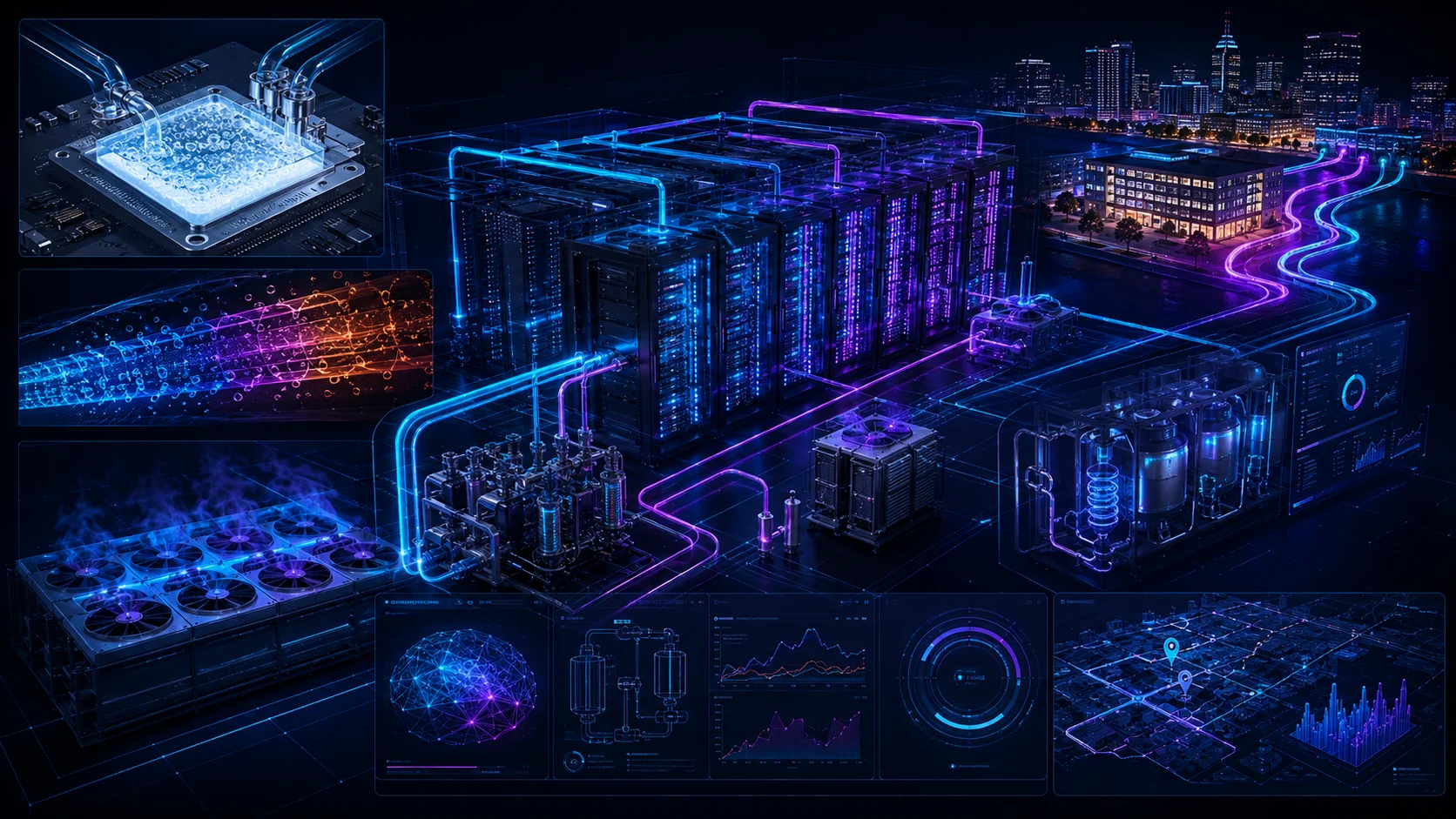
The defensible 2026 strategy is often hybrid: conventional air for support and moderate-density loads, direct-to-chip for qualified AI racks, rear-door exchangers for transition areas, and a heat-rejection system selected for the actual climate, water position, acoustic envelope, land plan, and resilience requirement. Phasing matters because an ultimate warm-water campus may begin with mixed IT generations and a much smaller initial load. Reserve routes, plant area, electrical capacity, water connections, structural support, and controls interfaces for credible future states without overbuilding every phase. Final selection requires coordinated MEP engineering, equipment-vendor confirmation, utility and water-provider confirmation, climate/weather design data, acoustic analysis, environmental and AHJ review where applicable, and alignment with the owner’s staffing, maintenance, spares, commissioning, and IT refresh strategy.
Current Technical Basis — August 2026
ASHRAE / NEMA / PNNL
AI Data Center Energy Performance Framework — Energy and Thermal EfficiencyCurrent 2026 framework covering AI rack density, liquid cooling, thermal efficiency, mixed cooling environments, and integrated energy strategy.
ASHRAE / NEMA / PNNL
AI Data Center Energy Performance Framework — Integrated Design PrinciplesCurrent integrated-design guidance addressing direct-to-chip cooling and AI/HPC thermal architecture.
NVIDIA
GB300 NVL72 Reference Architecture / Platform InformationExample of current rack-scale AI infrastructure using liquid-cooled architecture and extreme rack power density.
Uptime Institute
Cooling Systems Survey 2025Industry adoption, density thresholds, direct-liquid-cooling drivers, maintenance concerns, and cooling-system trends.
Uptime Institute
Dry Cooling Energy Performance Can Rival Evaporative Cooling2026 analysis of dry, adiabatic, and evaporative heat-rejection performance across climate zones.
Open Compute Project
Cooling Environments — Cold PlateIndustry work on cold plates, coolant fluids, CDUs, quick disconnects, blind-mate interfaces, reliability, interoperability, and serviceability.
Technical basis reviewed August 2026. Cooling technology, equipment capability, vendor qualification, and industry guidance continue to evolve; project decisions should use the latest applicable manufacturer data and professional engineering analysis.
Capacity-delivery review checklist
What to verify before the next release gate.
- Rack-density distribution and future IT generations defined
- Liquid capture ratio and residual air load quantified
- IT-platform coolant and temperature requirements confirmed
- Complete chip-to-ambient thermal chain modeled
- Hourly climate and extreme design conditions tested
- Heat-rejection land, setbacks, and service access reserved
- Water source, quality, treatment, and curtailment exposure confirmed
- Electrical energy and peak-demand impacts compared
- Acoustic performance evaluated at sensitive receptors
- CDU, pump, valve, and control failure modes tested
- Leak detection, isolation, drainage, and response procedures defined
- Materials compatibility and water chemistry requirements assigned
- Phasing and mixed air/liquid operation coordinated
- Maintenance bypasses, lifting, spares, and technician training planned
- Vendor warranties and equipment qualification confirmed
- Commissioning and integrated load-testing strategy established
What DCFR would flag
Delivery risks that should be visible early.
DCFR would flag a cooling concept selected from average rack density rather than the actual density distribution; liquid cooling without a defined IT platform, capture ratio, CDU boundary, or residual air load; water assumptions unsupported by provider confirmation; heat rejection sized without design-weather and degraded-mode analysis; plant that exceeds available land or acoustic limits; and efficiency claims that omit pumps, fans, chillers, redundancy, partial load, water treatment, or maintenance states.
Professional confirmation required
Items requiring project-specific validation.
Final cooling selection requires project-specific MEP engineering, equipment and IT-vendor confirmation, utility and water-provider confirmation, current climate/weather design data, acoustic and environmental analysis, controls and commissioning development, applicable AHJ review, and approval by the owner’s operations organization. Planning-grade comparisons are not final equipment selections, performance guarantees, or water and utility commitments.
Final takeaway
The most efficient cooling architecture is the one that reliably serves the actual workload within the site’s climate, power, water, land, noise, phasing, and operating constraints. In 2026, that answer is increasingly liquid-assisted—but it remains site- and platform-dependent.
Surface site, code, utility, and delivery risk before it becomes expensive.
DCFR converts early assumptions into planning-grade flags, confirmation registers, and decision-ready feasibility outputs.