
DCFR Insight 24 / Campus Planning + Capacity Delivery
Capacity DeliveryData Center Campus Master Planning: Power, Phasing, Cooling, and Expansion
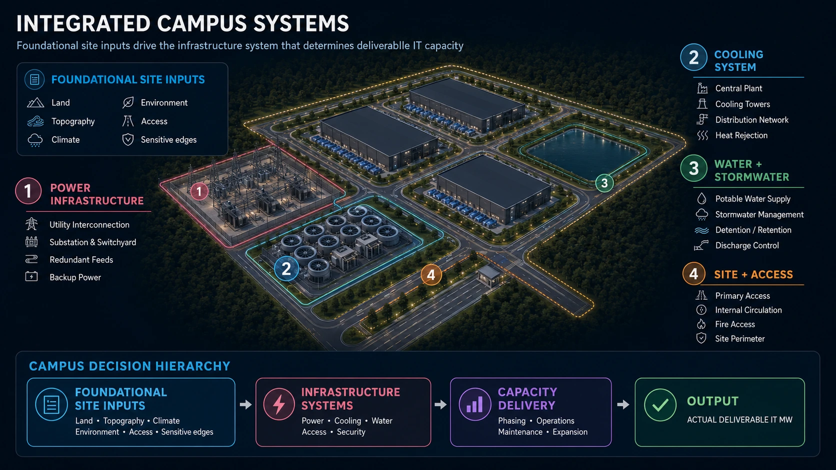
A data center campus is not a collection of buildings. It is an expandable infrastructure system where power, cooling, roads, fire access, stormwater, security, logistics, maintenance, and future expansion all compete for the same land. The master plan must therefore answer a more important question than how many buildings fit: how much reliable IT capacity can this parcel actually deliver through its full build-out?
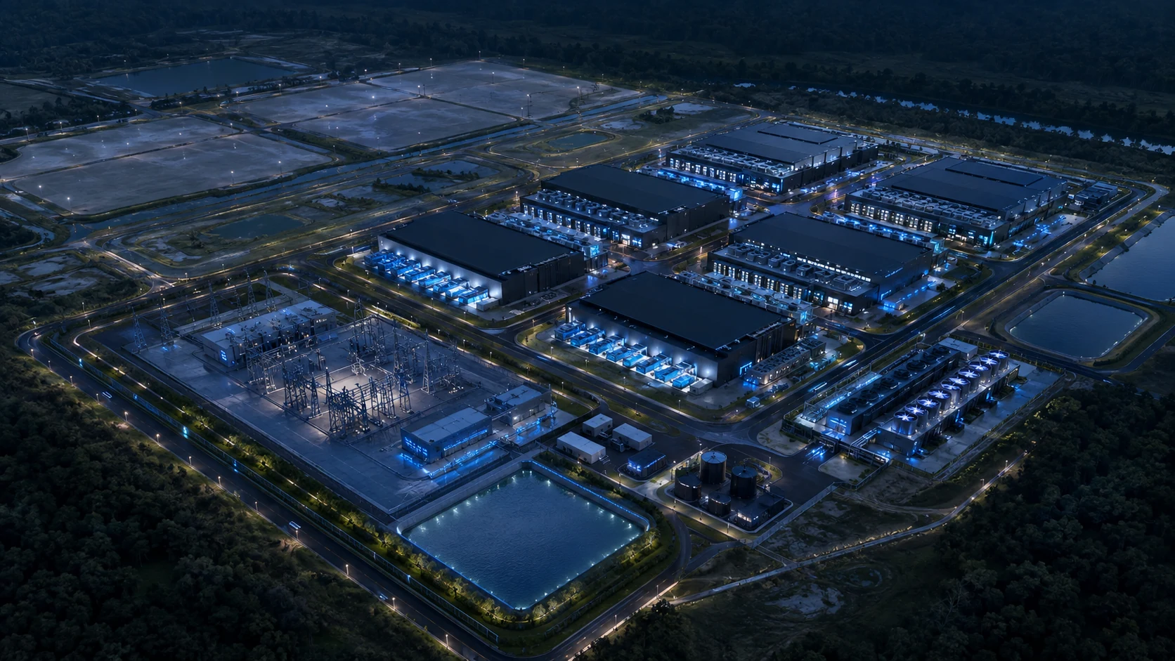
A campus should be planned backward from ultimate capacity
The first question in campus planning should not be where the first building goes. It should be: what is the ultimate capacity this site is expected to deliver, and how will the campus reach that capacity without Phase 1 obstructing Phase 2, Phase 3, or the final build-out? That requires an early planning basis for ultimate IT MW or GW, rack-density distribution, likely building count, repeatable modules, electrical topology, cooling architecture, phasing, road and fire access, grading, stormwater, security, future utility corridors, construction logistics and expansion reserve. The principle is simple: plan the ultimate campus first, then phase backward to Day 1. A road that works beautifully for Phase 1 can block a future electrical corridor. A mechanical yard can consume the most efficient expansion pad. A detention facility can occupy land assumed to be future capacity. The final-state logic therefore has to be understood before the first phase is optimized. Megawatts do not create the campus. Geometry does.
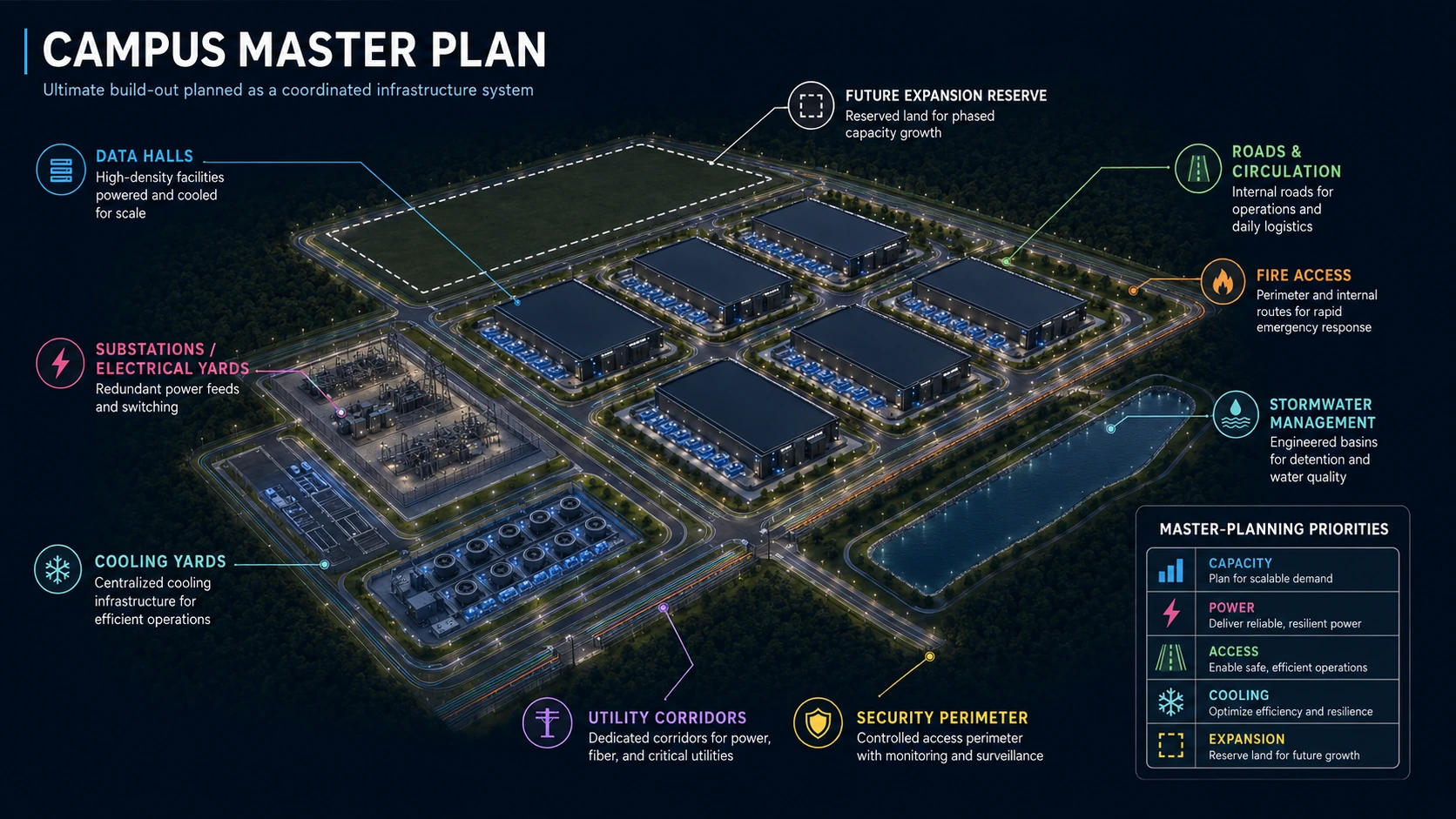
Simplified Steps: How to Design a Data Center Campus
At a high level, I would organize data center campus planning into these ten steps. The sequence is intentionally simple, but each step should be tested iteratively because power, architecture, cooling, civil infrastructure, operations, and future expansion continuously influence one another.
- 1
Define the ultimate IT capacity and phasing
Establish the ultimate MW or GW target, expected rack-density distribution, and how much usable capacity needs to come online in each phase. Plan the ultimate campus first, then work backward to Phase 1.
- 2
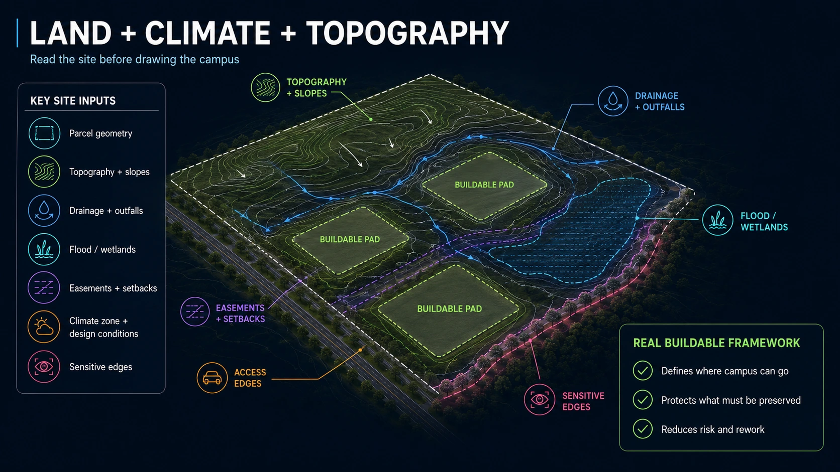
Read the land, climate, and topography
Establish the real buildable framework from parcel geometry, topography, drainage, environmental constraints, access, sensitive edges, and climatic design conditions before committing major campus geometry.
- 3
Establish the power and utility backbone
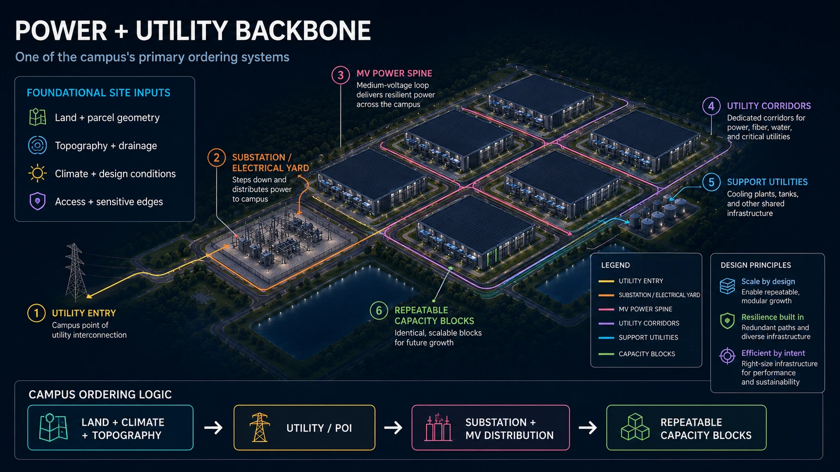
Confirm the utility entry strategy, substations, transformer zones, medium-voltage distribution, and protected utility corridors. Make sure future phases can connect without major rework of operating infrastructure.
- 4
Solve roads, truck access, and fire access
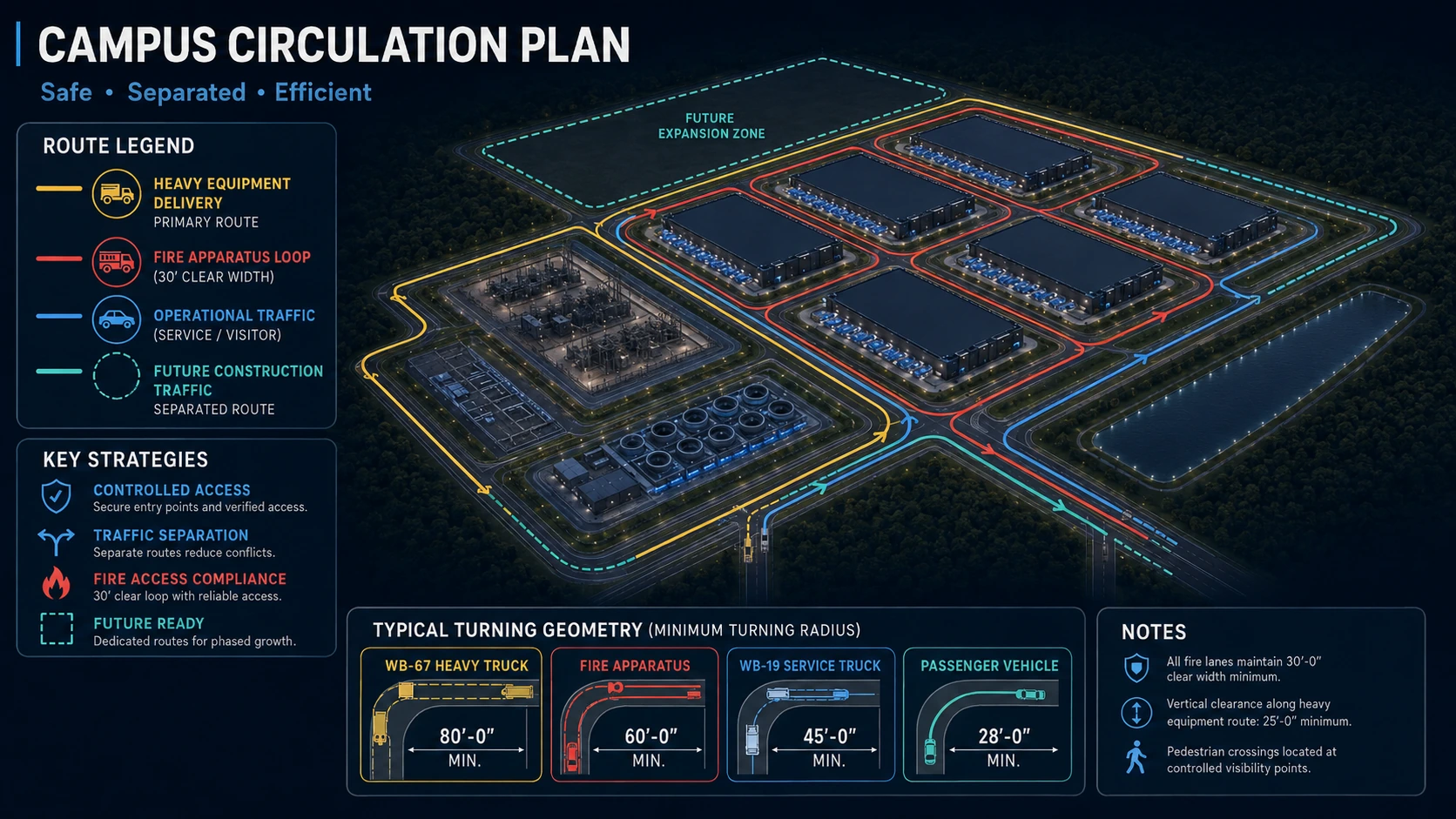
Establish secure entry, primary circulation, heavy-equipment delivery routes, fire-apparatus access, maintenance routes, and future equipment-replacement paths before the campus becomes too dense.
- 5
Create repeatable capacity blocks
Organize the campus around repeatable data-center modules rather than unrelated buildings. Coordinate each block with its electrical, cooling, service, resilience, and expansion requirements.
- 6
Coordinate cooling and water
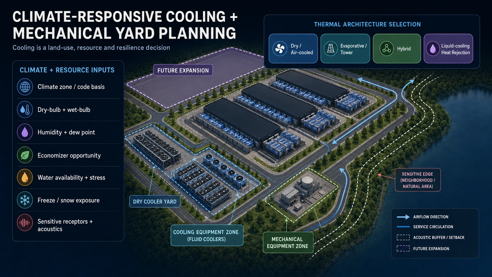
Allocate sufficient land for the actual thermal architecture. Consider climatic design conditions, heat rejection, airflow, water availability and stress, electrical demand, maintenance access, acoustics, and proximity to sensitive neighbors.
- 7
Develop grading, drainage, and stormwater
Develop the grading and drainage systems within the buildable framework established during early site feasibility, including detention or retention, outfalls, erosion control, and flood-resilient infrastructure.
- 8
Protect security and sensitive edges
Coordinate the secure perimeter, controlled access, setbacks, acoustic buffers, equipment orientation, and relationships between infrastructure and nearby residential or other sensitive uses.
- 9
Plan phasing, replacement, and expansion
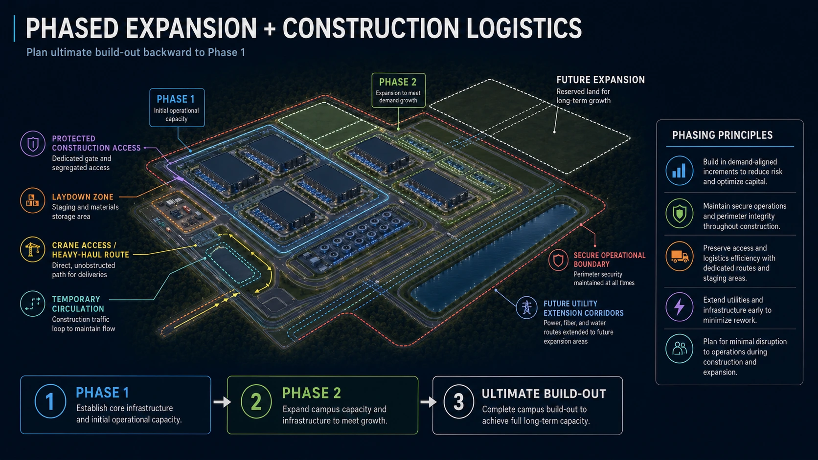
Make future phases constructible while earlier halls operate, and preserve construction access, secure boundaries, utility tie-ins, crane positions, heavy-haul routes, equipment replacement paths, and real expansion corridors.
- 10
Calculate the actual deliverable capacity
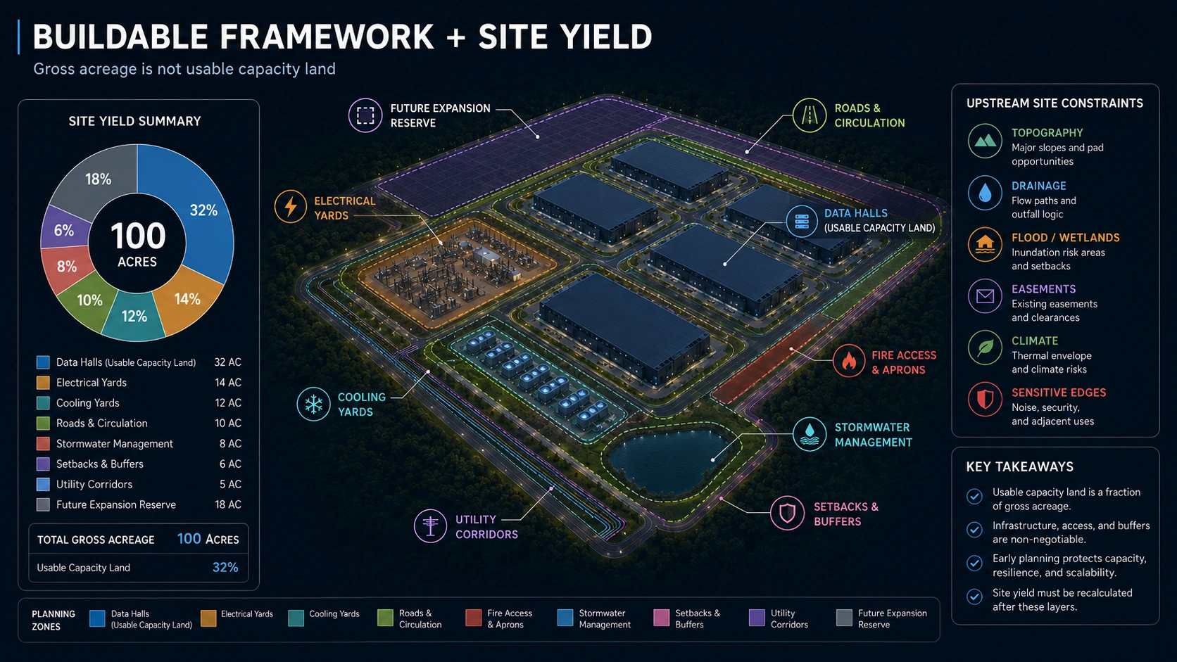
Recalculate site yield after buildings, electrical infrastructure, cooling, roads, fire access, stormwater, security, setbacks, utilities, and future expansion consume their required land. The final question is: how many reliable IT megawatts can this parcel actually deliver?
Plan the ultimate campus first. Phase backward to Day 1.
Climate is an upstream campus-planning input, not a late sustainability check
Climate affects the campus before cooling equipment is selected. It informs thermal architecture, envelope performance, structural loading, civil design, electrical equipment conditions, water strategy, resilience, and sustainability. Early site feasibility should therefore connect parcel geometry and topography with drainage, environmental constraints, sensitive edges, access, and climate. This combined reading establishes a credible buildable framework; later grading, drainage, and stormwater design then develops that framework rather than discovering its basic constraints after the campus layout is fixed.
What Actually Consumes Data Center Campus Land?
| Land-use component | Why it matters to capacity delivery |
|---|---|
| Data-center buildings | Primary location of usable IT capacity |
| Substations | Utility interface and electrical capacity blocks |
| Transformer / switchgear yards | Electrical distribution footprint and service access |
| Generator / fuel areas | Backup-power infrastructure, separation and replacement access where applicable |
| Cooling yards | Thermal capacity, water exposure, acoustic burden and maintenance area |
| Roads and truck courts | Operations, delivery, maintenance and heavy-equipment movement |
| Fire access | Protected life-safety geometry that cannot be treated as leftover roadway |
| Stormwater | Can materially reduce usable buildable area |
| Setbacks and buffers | Zoning, utility, environmental, security and acoustic constraints |
| Security perimeter | Controlled access, clear zones, gates and operational separation |
| Utility corridors | Power, fiber, water, sewer, controls and future infrastructure |
| Construction logistics | Determines whether later phases can be built beside live operations |
| Future expansion reserve | Only real capacity when utilities, roads, cooling and civil systems can actually serve it |
Gross acreage is not usable capacity acreage. Site yield should be calculated only after the infrastructure, access, civil, security and future-growth requirements of the campus have been applied.
Climate zone and climatic design conditions serve different purposes
Climate zone is not a complete climatic analysis. The team should identify the applicable climate-zone framework, then evaluate project-specific design dry-bulb temperature, wet-bulb temperature, humidity, dew point, freeze exposure, snow and ice conditions, wind, extreme precipitation, water availability, and water stress. Those inputs can affect cooling-system performance, envelope assemblies, structural criteria, electrical equipment ratings, water use, drainage, operating modes, and resilience. Applicable standards, weather data, utility information, water-resource conditions, and engineering criteria should be confirmed for the actual location rather than inferred from a broad climate-zone label.
Start with capacity, but do not confuse megawatts with site feasibility
A statement such as ‘this parcel should support 300 MW’ is only a hypothesis until the campus geometry proves it. A utility allocation does not automatically mean the parcel can physically accommodate the facilities required to consume that power. The site must fit data halls, substations, transformer and switchgear yards, generators where required, cooling infrastructure, utility corridors, roads, truck courts, fire access, stormwater, setbacks, security, support functions, construction logistics and real future expansion. Only after those systems are fitted together can the team establish credible deliverable capacity. Gross parcel acreage is therefore a poor proxy for data-center capacity. The better question is: how many usable IT megawatts can the parcel deliver after the complete infrastructure system consumes the land it requires? That is a site-fit calculation, not simply an acreage calculation.
Establish the electrical backbone as one of the first ordering systems
Power feasibility is one of the earliest campus-planning gates. The team needs to understand the utility point of interconnection, transmission or distribution interface, substation requirements, transformer strategy, medium-voltage distribution, redundancy topology, duct banks, utility corridors, generator strategy where applicable, future electrical expansion and major-equipment replacement access. This does not mean designing the substation in isolation and arranging everything else afterward. Power, architecture, civil, cooling and access must evolve iteratively. But the electrical backbone frequently becomes one of the primary ordering systems because a campus geometry that cannot efficiently connect utility power to IT load is largely theoretical. Without a credible path from the utility to the rack, the master plan is only a diagram.
Campus Planning Decision Matrix
| Campus strategy | Primary strength | Primary risk | Best application |
|---|---|---|---|
| Central infrastructure core | Efficient concentration of utilities and support plant | Central bottlenecks can constrain later expansion | Compact parcels with strong centralized utility logic |
| Distributed capacity clusters | Strong phasing flexibility and local infrastructure relationships | Can duplicate corridors, yards and support infrastructure | Large or irregular campuses requiring independent growth zones |
| Repeatable modular pods | Fast replication, procurement consistency and predictable commissioning | Requires disciplined early standardization and interface control | Fast-growth multi-phase AI campuses |
| Spine-and-branch campus | Clear infrastructure hierarchy and future expansion logic | Poor early spine decisions can propagate into every later phase | Large phased campuses with repeatable capacity blocks |
No campus topology is universally optimal. DCFR should compare alternative layouts against parcel geometry, utility entry, capacity target, phasing, civil constraints, cooling architecture, security, operations, maintainability and future construction.
Building placement and power topology should evolve together
The question ‘Should the building or substation be located first?’ creates a false choice. Electrical topology, repeatable building modules, circulation, cooling and civil constraints should be developed together. Building placement affects cable distance, fire access, cooling yards, service zones, grading and construction logistics. Electrical placement affects roads, expansion corridors, security and future building pads. Cooling affects acreage, acoustics and water strategy. Civil engineering affects nearly everything. The architectural role at this stage is therefore integration rather than disciplinary sequencing: translating many technical requirements into one physically coherent campus.
Use repeatable capacity blocks instead of unrelated buildings
At large campus scale, especially for AI infrastructure, it is useful to think in repeatable capacity blocks. A capacity block can combine data-hall capacity, electrical infrastructure, cooling infrastructure, support areas, service access, controls and a defined resilience strategy. The actual block size is project-specific, but the logic is powerful because it creates repeatability. Instead of asking how many buildings can fit, ask how many complete operational capacity blocks the parcel can support. Repeatable blocks can improve design speed, procurement consistency, construction repetition, commissioning, operations, maintenance and future expansion. The goal is not rigid sameness. It is to establish predictable interfaces so the campus grows as a system rather than as a collection of custom one-off projects.
Gigawatt campuses should be treated as infrastructure programs
At 500 MW, 1 GW or larger scales, the mental model changes. The project is no longer simply a large building development; it is an infrastructure program. Multiple substations, utility feeds, cooling systems, major civil works, transmission coordination, construction zones, commissioning sequences and long utility corridors may be required. The master plan should therefore investigate whether repeatable capacity blocks can be energized and commissioned incrementally. The commercial objective is often not merely to complete the campus. It is to deliver usable compute capacity as early as possible while preserving the path to ultimate build-out. That requirement can materially change the phasing, utility and construction strategy.
Solve road, truck and fire access before the campus becomes too dense
A building can fit geometrically while the campus still fails operationally. Data-center sites require circulation for fire apparatus, transformers, generators, chillers, cooling modules, fuel deliveries where applicable, heavy-haul transport, cranes, maintenance vehicles and construction traffic. The team should test whether a transformer can reach its installed location and whether it can be replaced years later, whether fire apparatus can continue to circulate after future phases are built, whether cranes can reach major mechanical equipment, and whether later construction can occur without crossing live secure operational zones. The road network must therefore be evaluated under normal, emergency, maintenance, replacement and construction conditions.
Construction logistics deserve their own master plan
One of the most common campus-planning mistakes is drawing the elegant final campus without drawing how it gets built. Multi-phase development should distinguish permanent operational circulation from temporary construction circulation. Later construction may require laydown, worker parking, oversized equipment deliveries, concrete traffic, crane pads, excavation corridors, temporary utilities, fencing, security transitions and construction offices. These activities can be incompatible with a live data-center operation. A professional master plan should test every transition—Phase 1 to Phase 2 to Phase 3 to ultimate build-out—and verify that each new phase can be constructed while previous phases remain secure and operational.
Fire access is not leftover roadway
Fire-apparatus access should be integrated into the site structure early and protected throughout later phases. The design team should coordinate roadway geometry, turning movements, hydrants, fire-department connections, security gates, clearances, pavement capacity, dead-end conditions and construction-phase access with the applicable code and responding authority. A future transformer yard, stormwater feature, parking area, security barrier or construction zone should never quietly compromise the emergency-response strategy. Fire access is therefore a protected campus system, not whatever roadway remains after other infrastructure has been placed.
Cooling architecture changes the master plan
Cooling is not merely an MEP equipment selection. It changes yard footprint, water demand, electrical demand, equipment density, airflow, plume or drift exposure where applicable, noise, service access, structural requirements and future expansion geometry. Dry heat rejection can reduce routine water exposure but may increase equipment area and acoustic burden. Tower-based systems introduce water supply, treatment, blowdown and plume considerations. Hybrid systems can balance energy, water and resilience but introduce additional infrastructure and operating modes. High-temperature direct-to-chip architectures can change both building and plant planning. The campus should therefore test credible complete thermal architectures rather than reserve a generic rectangle labeled ‘mechanical yard.’ The real question is how heat moves from silicon to atmosphere and what that complete chain requires from the site.
Keep major acoustic sources away from sensitive edges where possible
Noise problems are often easier and less expensive to solve through master planning than through late-stage mitigation. Potential sources include cooling equipment, generator testing, transformers, fans, chillers and truck circulation. Where residential or other sensitive receptors are nearby, the campus should use distance, equipment orientation, building shielding, berms, barriers, enclosures and appropriate equipment selection as part of the layout strategy. The first mitigation should often be better geometry. Intelligent placement of a cooling or generator yard can prevent a much more difficult acoustic problem later.
Stormwater can quietly eliminate large amounts of usable capacity
A parcel that looks generous on an aerial image can become highly constrained after civil systems are considered. Campus feasibility should evaluate grading, drainage, detention or retention requirements, underground stormwater systems where appropriate, bioswales, flood conditions, wetlands, erosion control, outfall constraints and utility conflicts. Stormwater should not be assigned to whatever land remains after architecture and electrical infrastructure are placed. On large campuses it is significant infrastructure in its own right. A poorly located stormwater system can eliminate a future data-hall pad, block a utility corridor or complicate later phases.
Separate incompatible uses intentionally
A data-center campus is not an undifferentiated industrial field. Substations, transformers, generators, fuel systems, cooling yards, data halls, administration, loading areas, security, parking, stormwater, air intakes and sensitive property edges have different operational, life-safety, environmental and acoustic requirements. Good campus planning creates an operational zoning system that deliberately coordinates those relationships. The objective is not merely orderly graphics. It is safer access, better maintainability, reduced conflict, clearer security and more predictable future expansion.
Future expansion must be real, not a rectangle labeled Future
An empty parcel next to Phase 1 does not automatically equal expansion capacity. Future expansion requires real power capacity, electrical connection paths, cooling capacity, utility routes, roads, fire access, drainage, security, construction logistics, replacement access and compatible grading. If those systems cannot serve the expansion pad, the reserve is largely theoretical. Future capacity should therefore be protected both physically and infrastructurally. Early phases must preserve the corridors, plant interfaces and access logic that later capacity will actually require.
Plan major-equipment replacement from the beginning
A campus that can be constructed but cannot later be maintained is incomplete. Transformers, generators, chillers, pumps, cooling modules, switchgear and other major equipment may eventually need replacement. The master plan should preserve heavy-haul access, crane positions, removable barriers, lifting zones, equipment clearances and maintenance bypasses. A useful test is simple: if this transformer fails years from now, can the operator physically remove and replace it without compromising live capacity? That question often reveals weaknesses that ordinary site-plan review misses.
Test the campus under failure and maintenance conditions
Master plans are usually drawn under ideal conditions, but real campuses operate under imperfect ones. The site should be tested with a road temporarily unavailable, equipment under maintenance, a cooling module out of service, an adjacent phase under construction, utility tie-in work underway, temporary crane access established, a major transformer or generator replacement in progress, and emergency response occurring simultaneously with normal operations. A resilient campus should continue functioning through credible degraded states. This is the site-planning equivalent of redundancy engineering.
The most common campus-planning mistake is optimizing Phase 1
Phase 1 matters because it establishes first capacity, but an aggressively optimized first phase can create severe downstream costs. It can consume the best utility corridor, interrupt the future power spine, block fire circulation, eliminate replacement access, occupy future capacity land or force later construction traffic through operating areas. Phase 1 should therefore be optimized inside the logic of the ultimate campus rather than treated as an independent project. The first building is not the campus. It is the first move in a long infrastructure sequence.
Speed to capacity comes from reducing future rework
Fast delivery does not mean skipping planning. Weak early planning often slows delivery because later teams must redesign infrastructure that should have been anticipated from the beginning. Strategies that can improve speed include repeatable building and electrical modules, standardized interfaces, protected utility corridors, early utility coordination, early AHJ engagement, disciplined long-lead decisions, independent construction zones, commissioning by capacity block and deliberate future-phase reservation. The useful principle is: standardize what should repeat and preserve flexibility where uncertainty remains. Speed to capacity comes from eliminating avoidable downstream decisions and rework.
Why architecture matters at campus scale
It is reasonable to ask whether campus planning is primarily electrical, mechanical and civil engineering. Those disciplines are essential, but somebody still has to integrate power, cooling, code, fire access, security, circulation, equipment yards, building separation, acoustics, stormwater, future phases and construction logistics into one physically coherent site. That integration is spatial. Architecture at campus scale therefore becomes infrastructure integration through geometry. The architect or architectural engineer adds value by translating many technical requirements into a master plan that can actually be permitted, constructed, maintained, expanded and operated.
What should exist very early in design?
Before detailed building design advances too far, the team should have an Ultimate Capacity Master Plan showing existing and future building modules, electrical spine, substations, cooling zones, primary roads, fire access, security, stormwater, utility corridors, construction logistics and expansion reserve. Alongside that drawing should be an Assumptions and Constraints Register. Important inputs should be classified as Confirmed, Planning Assumption, Constraint or Confirmation Required. Utility capacity, rack density, cooling technology, water availability, stormwater requirements, generator quantities, major equipment dimensions, acoustic limits and AHJ interpretations should never quietly migrate from unverified assumptions into permanent design decisions.
Overlay Entitlement Commitments on the Ultimate-Campus Plan
The master plan should show not only technical infrastructure but also the development envelope actually approved or proposed for approval. Overlay maximum building area and height, setbacks, buffers, protected views, equipment-yard limits, substation and transmission corridors, access points, road conditions, noise criteria, water and discharge commitments, landscaping, lighting, construction hours, and phase triggers. Test every intermediate and ultimate phase against that envelope. When a commitment changes, identify its effect on capacity, circulation, utilities, cost, schedule, Basis of Design, and future-site standards before accepting it.
- 1
1. Map the approval envelope
Place entitlement plans, proffers, conditions, staff requirements, utility agreements, and permit constraints on the same controlled campus base.
- 2
2. Test every phase
Confirm that Phase 1, intermediate states, ultimate buildout, construction access, and equipment replacement remain compliant.
- 3
3. Trace commitments
Assign every obligation to an owner, BOD or standard location, design record, verification method, and operational handoff.
- 4
4. Feed lessons forward
Convert recurring approval constraints and successful responses into the next version of the owner standards without treating them as universal requirements.
Entitlement Overlay on the Campus Plan
| Approved or proposed control | Master-plan test | Downstream record | Verification and handoff |
|---|---|---|---|
| Building area, height, setbacks and buffers | Every phase remains inside the development envelope | Site standard, civil and architectural BOD | Permit comparison, survey and as-built |
| Noise and testing commitments | Ultimate equipment and operating scenarios meet the criteria | Acoustic basis, equipment requirements and controls narrative | Commissioning test and operating procedure |
| Access, traffic and construction routing | Permanent and temporary movements remain feasible through buildout | Civil basis and logistics standard | Agency acceptance and field logistics audit |
| Water, wastewater and stormwater obligations | Phase demand, discharge, outfalls and maintenance remain executable | Utility and civil BOD | Metering, permit closure and operations reporting |
| Landscape, lighting and visual commitments | Expansion and replacement work preserve required mitigation | Landscape and exterior-lighting standards | Inspection, closeout and maintenance plan |
The approval overlay should be revised with every entitlement action, condition change, phase plan, and owner-standard update.
How DCFR would evaluate a data center campus master plan
DCFR should treat campus planning as a sequence of feasibility gates rather than a drawing exercise. Each gate tests whether the proposed campus remains compatible with the intended compute capacity, utility strategy, parcel geometry, civil constraints, life safety, cooling, phasing, construction logistics, maintainability and future expansion.
13 Data Center Campus Master-Planning Decision Gates
- Ultimate IT capacity — define the credible ultimate MW or GW target and rack-density distribution.
- Phasing — define how much usable capacity must be delivered in each phase and what must remain reserved for later phases.
- Power topology — confirm that utility entry, substations and distribution can efficiently reach every planned capacity block.
- Building modules — establish a repeatable deployment logic rather than unrelated individual buildings.
- Road and fire access — verify operations, emergency response, heavy equipment, maintenance and replacement access.
- Cooling — confirm that the complete thermal architecture physically fits the parcel and remains compatible with water, energy and acoustic constraints.
- Civil — quantify land consumed by grading, stormwater, flood conditions, drainage and environmental constraints.
- Operational zoning — separate incompatible uses and protect security, safety and maintainability.
- Construction logistics — prove that later phases can be built while earlier phases remain live and secure.
- Acoustics and community exposure — evaluate sensitive campus edges before equipment locations become fixed.
- Replacement and maintenance — preserve realistic paths for heavy equipment, cranes and major plant replacement.
- Expansion infrastructure — confirm that future pads can actually receive power, cooling, roads, utilities, fire access and construction access.
- Capacity yield — calculate how many IT megawatts remain deliverable after all campus constraints and infrastructure consume land.
The master plan is successful only if it preserves the path from the first energized megawatt to the ultimate campus capacity.
DCFR Campus Planning Decision Flow
- Ultimate capacity
- Phasing
- Power topology
- Capacity blocks
- Road + fire access
- Cooling
- Civil + stormwater
- Operational zoning
- Construction logistics
- Acoustics
- Maintenance
- Expansion infrastructure
- Capacity yield
Campus Master-Planning Red Flags
- Phase 1 is drawn without an ultimate-campus build-out strategy.
- The MW claim is based primarily on gross acreage rather than complete infrastructure fit.
- The utility point of interconnection or substation strategy is unconfirmed.
- The future electrical or utility spine is blocked by early development.
- Cooling infrastructure is represented only as generic leftover yard space.
- Stormwater is assigned after buildings and electrical infrastructure are fixed.
- Heavy-equipment replacement routes are not preserved.
- Fire access becomes compromised as later phases are added.
- Future expansion pads are shown without credible power, cooling, utility or access paths.
- Later construction traffic crosses operating secure areas.
- Sensitive acoustic receptors or community edges are ignored.
- Later phases require major rework of live infrastructure.
- Ultimate campus capacity is based on average rack density without testing credible high-density deployment scenarios.
Capacity-delivery review checklist
What to verify before the next release gate.
- Ultimate campus IT-capacity target defined
- Rack-density distribution and future workload assumptions documented
- Phasing sequence defined from Phase 1 through ultimate build-out
- Utility point of interconnection and power topology identified
- Substation, transformer and electrical distribution zones reserved
- Repeatable capacity-block logic tested
- Truck, heavy-equipment and maintenance circulation tested
- Fire apparatus access protected through all phases
- Cooling and heat-rejection yard requirements reserved
- Stormwater, grading, flood and drainage constraints evaluated
- Security perimeter and controlled-entry strategy established
- Sensitive acoustic/community edges identified
- Operational and construction circulation separated where practical
- Future utility corridors protected
- Major-equipment replacement routes preserved
- Future expansion pads confirmed to have real service paths
- Intermediate construction and operational states tested
- Gross acreage converted into planning-level usable capacity yield
- Assumptions and Constraints Register created
- Utility, civil, MEP, vendor, code and AHJ confirmations clearly identified
- Entitlement plans, proffers, conditions and public commitments overlaid on the ultimate-campus plan
- Approval obligations traced into the BOD, design records, verification and operations
What DCFR would flag
Delivery risks that should be visible early.
DCFR would flag a campus whose capacity claim is based primarily on gross acreage or utility megawatts without complete site-fit testing; Phase 1 layouts that block future power, roads, fire access or construction; generic cooling yards without a defined thermal strategy; stormwater treated as leftover land; future pads without real utility and access paths; major equipment that cannot be replaced; later construction that crosses live secure operations; and master plans that do not calculate the actual IT capacity remaining after infrastructure consumes the parcel.
Professional confirmation required
Items requiring project-specific validation.
Final campus planning requires project-specific civil, electrical, mechanical, structural, fire-protection, security, acoustic and environmental engineering; current survey and geotechnical information; utility and water-provider confirmation; equipment-vendor data; applicable zoning and code analysis; fire-department and AHJ coordination; and alignment with the owner's operating, construction and commissioning strategy. DCFR master-planning analysis is planning-grade feasibility intelligence and is not a final engineered site plan, utility commitment, permit approval or construction document.
Final takeaway
A data center campus succeeds when land is treated as an infrastructure system rather than empty space. Its true capacity is determined not only by utility megawatts or gross acreage but by whether power, buildings, cooling, roads, fire access, stormwater, security, construction, maintenance and future expansion can coexist through every phase. The best master plan is not necessarily the densest plan—it is the one that delivers the greatest reliable, maintainable and expandable compute capacity with acceptable execution risk.
Surface site, code, utility, and delivery risk before it becomes expensive.
DCFR converts early assumptions into planning-grade flags, confirmation registers, and decision-ready feasibility outputs.