
DCFR Insight 25 / Sustainability + Net Zero + LEED (Leadership in Energy and Environmental Design) Platinum
SustainabilityCan a Data Center Be Net Zero?
A developer-focused guide to integrating data center sustainability, Net-Zero energy and carbon performance, and a credible LEED Platinum pathway.
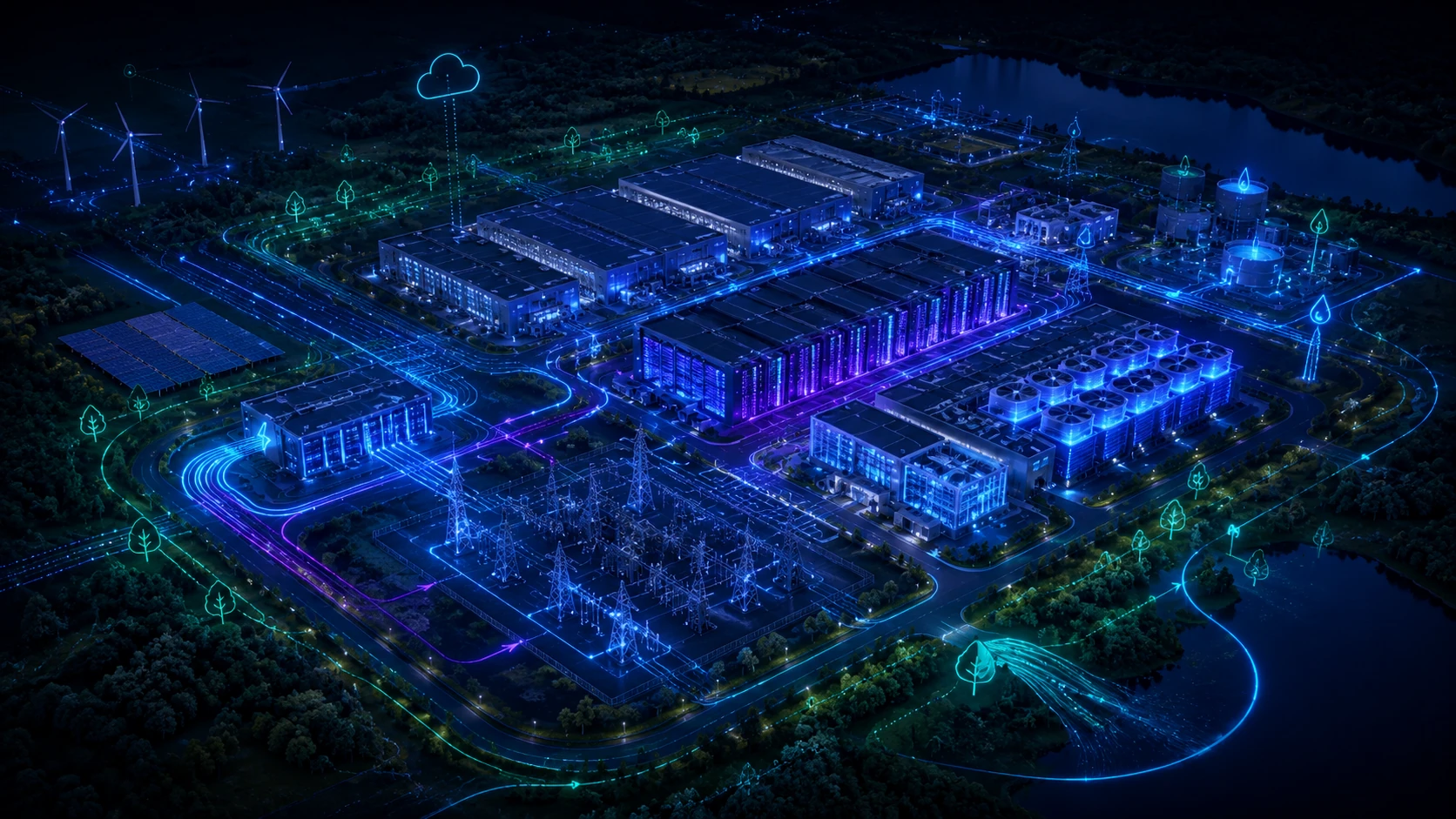
Can a Data Center Really Be Net Zero?
Yes—but only after the developer defines what the claim covers, how it is calculated, the accounting period, and how it will be verified. Efficiency delivers more useful compute per unit of energy; it is not itself a zero-energy claim. Net-Zero Energy balances defined energy use and qualifying supply under a stated method. Net-Zero Carbon addresses defined greenhouse-gas emissions and may use an operational or lifecycle boundary. Annual renewable matching does not prove that clean generation served the facility in every location and hour; 24/7 carbon-free energy seeks a more granular location- and time-matched outcome. A continuous hyperscale artificial intelligence load will generally exceed credible rooftop-solar production, so the strategy must combine demand reduction, grid and procurement pathways, and evidence. Developers should establish the boundary, residual impacts, energy attributes, measurement period, and verification method before underwriting the claim.
Efficiency first. Clean energy second. Verified performance last.
What Does the Sustainability Claim Actually Mean?
| Claim | What it establishes | What it does not establish |
|---|---|---|
| Energy efficient | Less energy for a defined service or compute output | Renewable supply, zero emissions, or whole-system sustainability |
| Annual renewable matching | Qualifying generation or attributes match a stated annual quantity | That clean electricity served the facility in every location and hour |
| Net-Zero Energy | An energy balance under a defined boundary, method, and period | Net-Zero Carbon or low lifecycle impact |
| Net-Zero Carbon | A balance or elimination of defined greenhouse-gas emissions | Zero energy, zero water, or every lifecycle impact |
| 24/7 carbon-free energy | Carbon-free electricity matched by location and hour under the stated method | Low embodied carbon, responsible water use, or LEED Platinum |
| LEED Platinum | The highest point-based LEED certification level plus applicable requirements | Automatic Net-Zero Energy or Net-Zero Carbon performance |
| LEED Zero | Separate recognition for an applicable measured operational-performance scope | LEED Platinum or every other zero outcome |
Every claim needs a defined boundary, methodology, accounting period, evidence, and applicable certification criteria.
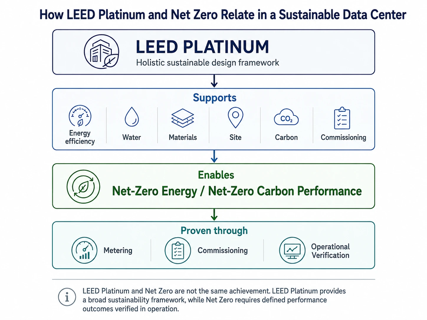
Map the Big Picture First: LEED Platinum and Net Zero Are Complementary
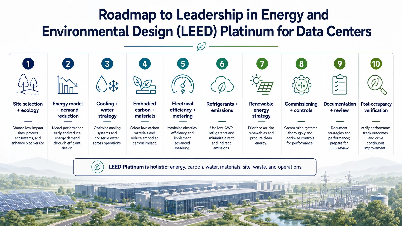
LEED Platinum is a holistic sustainable-design and certification framework addressing energy, water, materials, site, carbon, ecology, commissioning, waste, quality of life, and other whole-building impacts. That framework can support Net-Zero Energy and/or Net-Zero Carbon, but the performance outcome still requires a declared boundary, metering, commissioning, and operational verification.
LEED Platinum establishes the holistic framework. Net Zero proves the defined performance outcome.
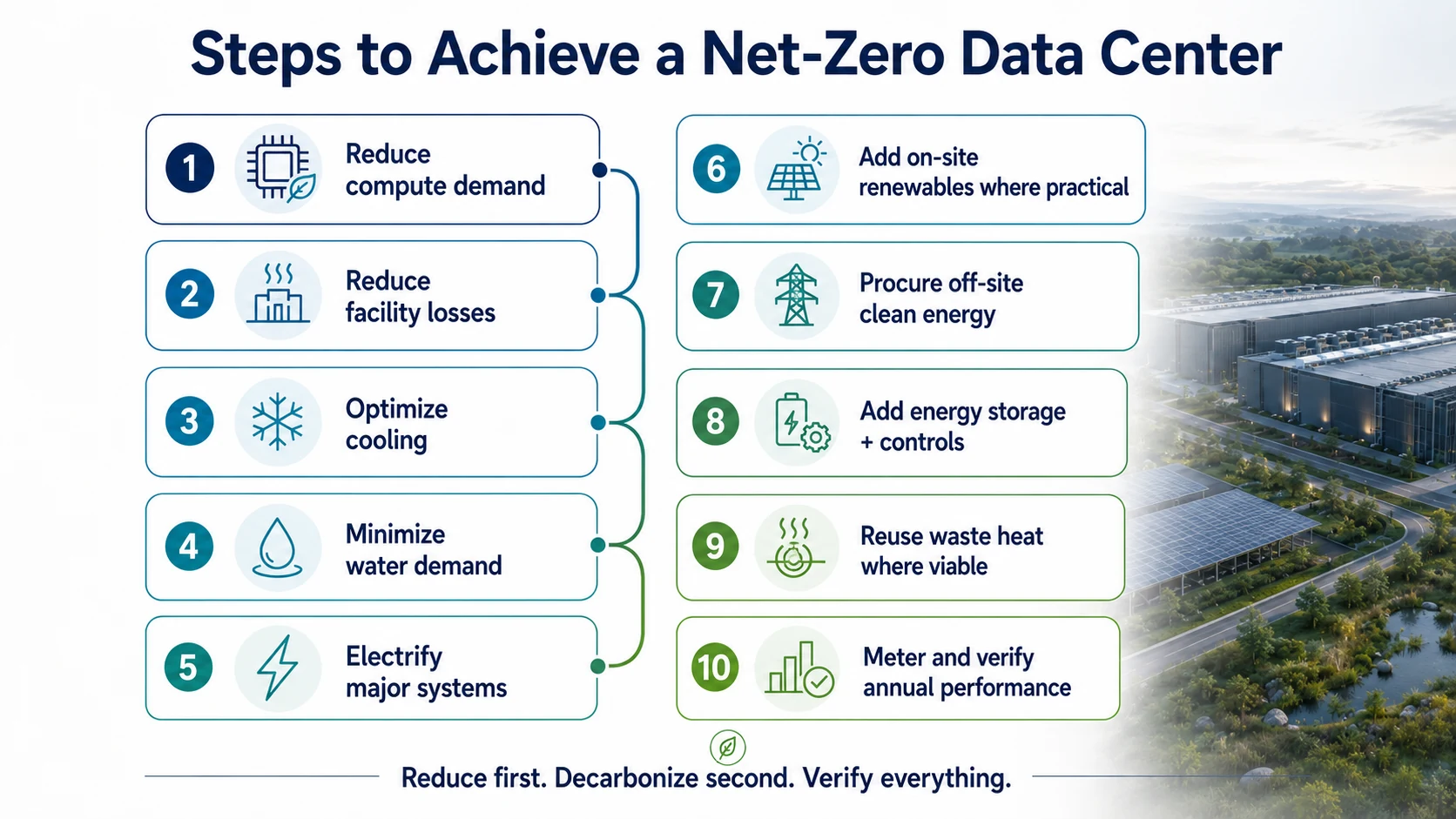
10 Steps to Move a Data Center Toward Net Zero
Turn the roadmap into ten owned work packages. Each step should produce a measurable design decision, calculation, specification, contract requirement, or acceptance record.
- Step 1
Define the IT Load Profile
Document hourly IT (Information Technology) demand, utilization, rack density, expected growth, and schedulable or flexible loads. Establish the load curve that every energy and infrastructure decision will use.
- Step 2
Quantify Facility Losses
Model losses through transformers, UPS (Uninterruptible Power Supply) systems, electrical distribution, fans, pumps, chillers, and heat rejection equipment at both full and part load. Identify where efficiency improvements produce meaningful annual savings.
- Step 3
Compare Complete Cooling Architectures
Evaluate complete cooling systems—not isolated equipment—against annual energy use, peak electrical demand, water use, reliability, noise, land demand, maintenance, and climate suitability.
- Step 4
Establish the Water Budget
Calculate annual and peak water demand by source, treatment requirement, discharge path, blowdown, and drought operating mode. Confirm that the cooling strategy remains feasible under water-constrained conditions.
- Step 5
Electrify Routine Loads
Identify heating, humidification, service vehicles, and other routine fossil-fuel loads that can be electrified. Document any residual combustion loads and why they remain necessary.
- Step 6
Size Onsite Renewables Realistically
Calculate buildable roof, canopy, and land area; hourly renewable yield; interconnection constraints; and realistic annual contribution. Do not treat nominal photovoltaic capacity as equivalent to continuous data center load.
- Step 7
Procure the Remaining Electricity
Define how residual electricity demand will be supplied through utility renewable programs or a Power Purchase Agreement (PPA). Document energy attributes, location, contract term, additionality assumptions, and treatment of future expansion.
- Step 8
Deploy Flexibility and Storage Deliberately
Define the role of controls, schedulable Information Technology (IT) loads, thermal storage, and Battery Energy Storage Systems (BESS). Include conversion losses and verify operating sequences through functional testing.
- Step 9
Validate Heat Reuse Against a Real Off-Taker
Do not claim heat reuse without a named customer or credible demand source. Test available temperature, hourly demand overlap, distance, distribution route, upgrading energy, capital cost, and commercial responsibility.
- Step 10
Lock the Metering and Accounting Boundary
Issue the meter schedule and carbon-accounting boundary before construction. After operation begins, reconcile utility meters, submeters, fuel consumption, renewable generation, purchased energy attributes, and exported heat records.
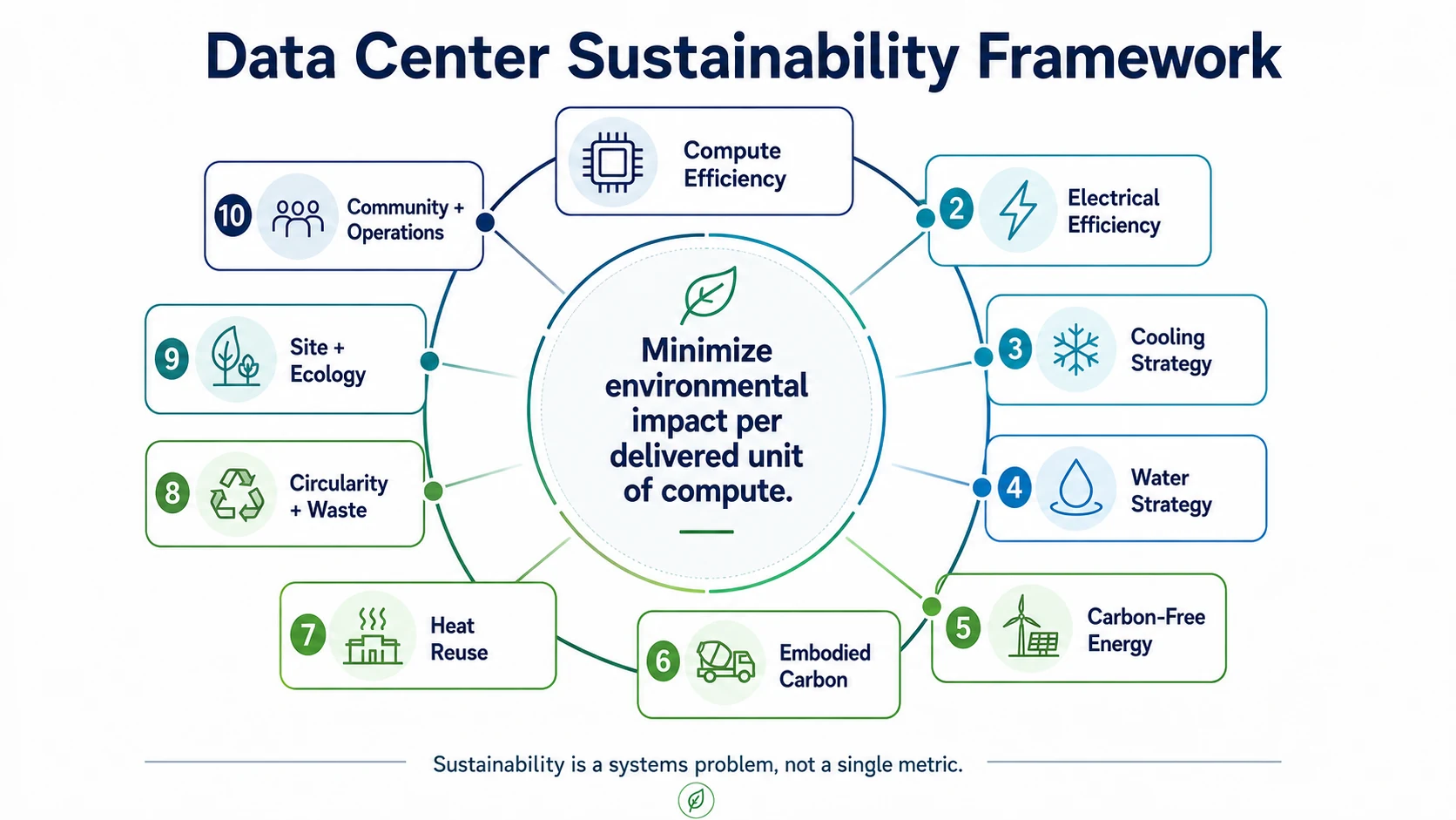
Data Center Sustainability Is a Systems Problem
A sustainable data center cannot be optimized around energy alone. Its performance emerges from the interaction of compute efficiency, electrical systems, cooling, water, carbon, materials, heat reuse, circularity, site ecology, and long-term operations. The goal is to minimize environmental impact per delivered unit of compute while preserving the capacity, resilience, reliability, and maintainability the facility requires. Use the framework as the primary system map, then turn each system into five project controls: an owner decision, a quantified analysis, a coordinated design action, a procurement or specification requirement, and a named verification deliverable. That translation—not another list of aspirations—is what makes the framework executable.
Start at the Silicon: Reduce Energy Before Producing More Energy
Begin with IT (Information Technology) utilization, workload scheduling, right-sized hardware, and performance per watt. Nearly every watt consumed by computing becomes heat, so unnecessary IT energy also creates upstream transformer, distribution, and UPS (Uninterruptible Power Supply) losses and downstream fan, pump, and heat-rejection demand. Model electrical efficiency across real load ranges, seasons, maintenance conditions, and failure modes; specify efficient power supplies, transformers, conductors, variable-speed equipment, and control resets; and meter conversion stages so losses remain visible. PUE (Power Usage Effectiveness) is useful for comparing facility overhead to IT energy within a declared boundary, but a low PUE alone does not prove low carbon, responsible water use, circular materials, good site outcomes, or comprehensive sustainability.
Cooling, Water, and Carbon Must Be Designed Together
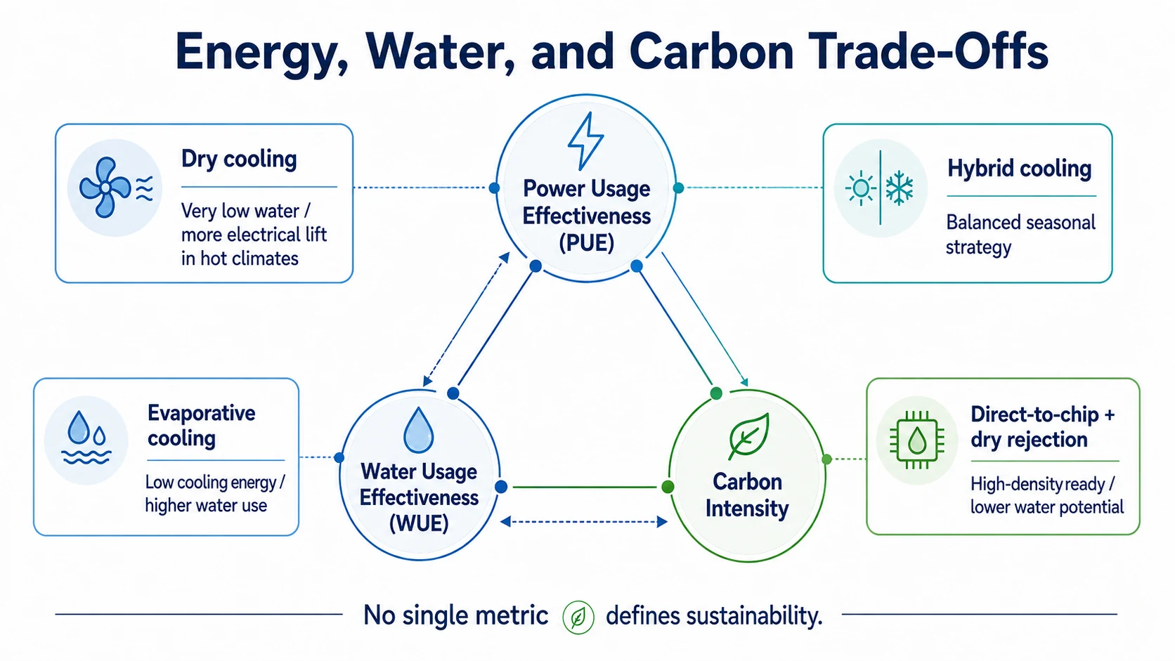
Select the complete thermal chain from chip to final heat rejection. The mechanical engineer must compare air, direct-to-chip, dry, evaporative, and hybrid schemes against the same IT profile and hourly weather file—not vendor design points. For each scheme calculate annual cooling energy, peak electrical load, annual and peak water withdrawal and consumption, source-water quality and treatment, drought-mode capacity, and hourly carbon. A direct-to-chip scheme still needs pumps, a CDU (Coolant Distribution Unit), coolant controls, service clearances, and a final heat sink. The architect and civil engineer must compare equipment footprint, land take, plume or drift, screening, and acoustic exposure; the operator must compare redundancy, maintenance, chemical handling, and failure recovery. Put guaranteed equipment duty, part-load efficiency, sound power, water quality limits, control modes, metering, factory tests, and functional tests in the procurement documents. Verify seasonal and drought sequences with trends after opening. PUE (Power Usage Effectiveness) and WUE (Water Usage Effectiveness) are outputs of this complete architecture; liquid cooling alone does not determine either result.
How a Data Center Moves Toward Net-Zero Energy and Net-Zero Carbon
Start with a modeled annual energy balance built from the hourly IT profile plus electrical and cooling losses, and state whether the boundary includes backup fuel, refrigerants, purchased utilities, exported energy, and lifecycle emissions. Estimate onsite generation from buildable roof or land area, shading, yield, interconnection, curtailment, and future phases—not nameplate capacity alone. For the residual, compare utility programs, offsite generation, and procurement contracts for location, deliverability, additionality, energy-attribute ownership, term, and expansion. Define whether storage provides ride-through, peak control, renewable shifting, or grid services; include round-trip losses, degradation, replacement, controls, and metering. Annual matching may support an annual claim, but the team must expose hourly supply-demand mismatch and cannot call it 24/7 carbon-free operation without location- and hour-matched evidence. The owner must approve the accounting method, the energy advisor must preserve attributes in contracts, the controls contractor must implement dispatch sequences, and closeout must reconcile the declared boundary to utility, fuel, generation, storage, and attribute records.
Backup Power, Refrigerants, and Hidden Operational Carbon
Emergency resilience and life safety remain mandatory constraints. Do not assume required backup generation can simply be removed. Quantify generator manufacture, routine testing, fuel delivery and storage, emergency operation, criteria pollutants, and greenhouse-gas emissions; evaluate batteries, microgrids, fuel cells, and lower-carbon fuels only where availability, compatibility, reliability, code, and AHJ (Authority Having Jurisdiction) acceptance are demonstrated. Refrigerant selection should balance safety, equipment availability, efficiency, and GWP (Global Warming Potential). Minimize charge, detect and record leakage, recover refrigerant during service and replacement, and include maintenance and end-of-life impacts in the operational-carbon plan.
Stop Throwing Useful Heat Away
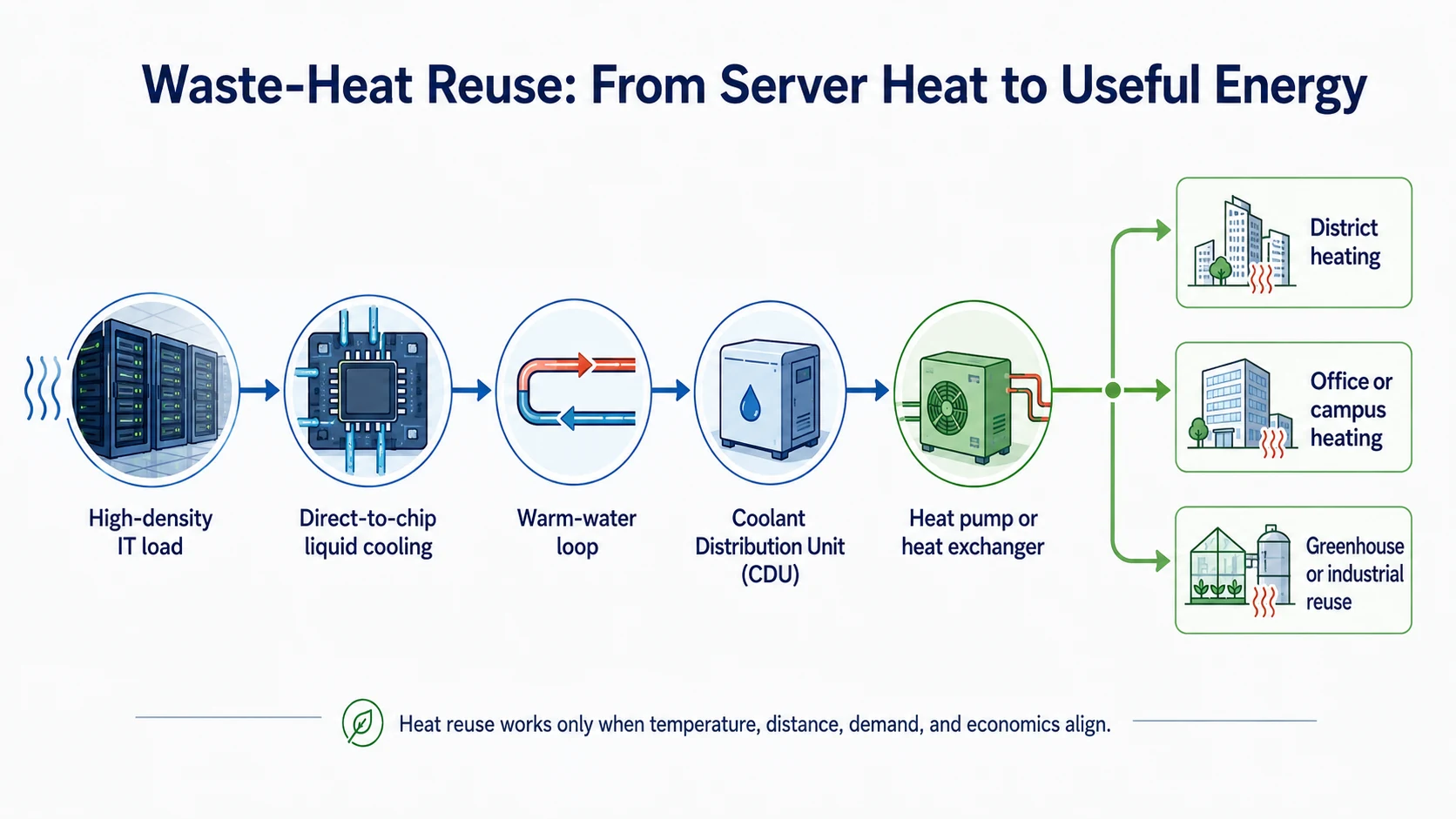
Do not claim reuse until a named heat customer is engaged. Record the customer's required supply and return temperatures and hourly demand profile; compare them with the data center's available temperature and hourly recoverable quantity. Survey distance, elevation, rights-of-way, and a buildable pipe route, then calculate pipe loss, pumping, heat-pump lift and energy, refrigerant impact, backup supply, and net useful heat. The owner must settle asset ownership, capital, tariff, outage responsibility, service level, and contract term before the architect preserves plant space and the engineers size connections. Specifications must define meters, controls, isolation, water quality, and test points. Closeout evidence is a commissioned interface plus customer and thermal-meter records showing useful delivered heat net of upgrading and pumping energy. A capped future connection is justified only by a documented customer probability, route, capacity, and commercial trigger.
Embodied Carbon and Circular Construction Matter Before the Servers Turn On
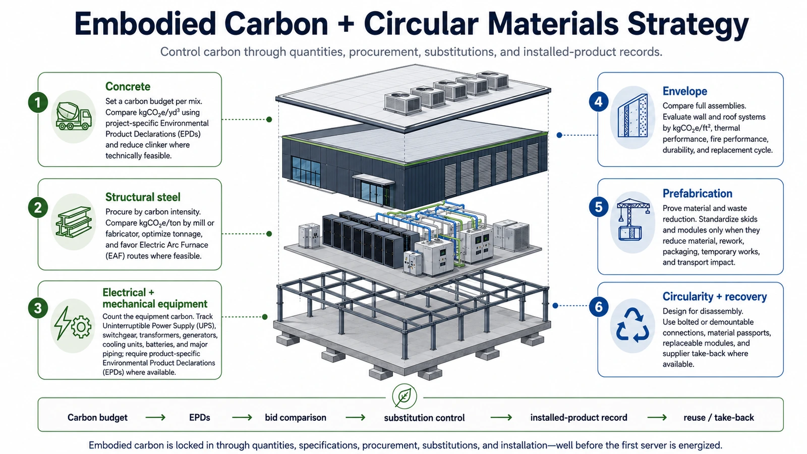
Run embodied carbon as a staged cost-and-quantity control. At Concept, the sustainability consultant establishes a whole-project LCA (Life Cycle Assessment) baseline and the owner approves its scope, reference study period, lifecycle modules, and initial carbon budget. At Schematic Design, the architect and structural engineer compare grids, spans, foundations, framing systems, structural-steel tonnage, reinforcing steel as a separate quantity, concrete volume and mix assumptions, façade area, complexity, and replacement life before the scheme locks. The MEP (Mechanical, Electrical, and Plumbing) engineers add major equipment and distribution quantities and request product or carbon data where available. At Design Development, update the budget by package and assign variance owners. At Construction Documents, require product-specific EPD (Environmental Product Declaration) data, report concrete mixes by actual GWP (Global Warming Potential), state calculation rules and submittal fields, set package limits where supportable, and require circularity measures such as accessible connections, replaceable modules, take-back, and recovery routes. At Procurement, the contractor compares bids on equivalent scope; prefabrication receives credit only after accounting for material, factory waste, transport, temporary works, and installation. No substitution is accepted on price or schedule alone: procurement must disclose quantity and product changes and obtain carbon review. During Construction, track installed mixes, steel, enclosure, equipment, waste, and destination records. At Closeout, reconcile installed quantities and EPDs against design assumptions, explain variances, and issue the as-built LCA and recovery information to the owner.
Sustainable Campus Planning Includes Land, Ecology, Water, Acoustics, and Community
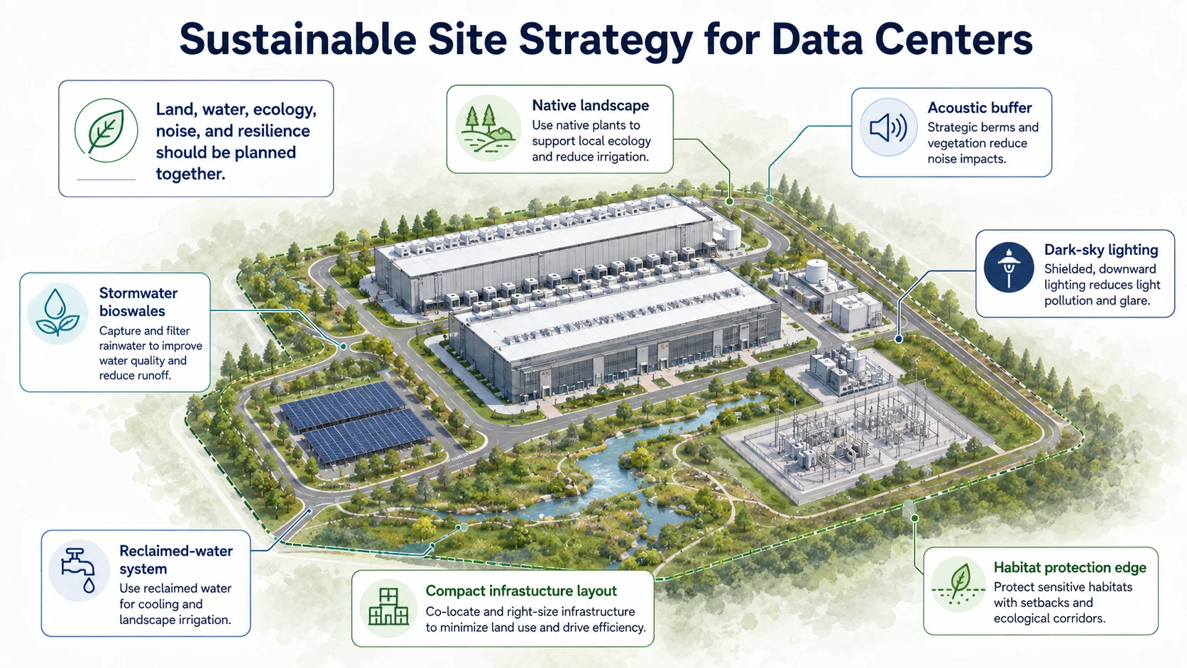
Before acquisition, the developer must compare candidate sites on disturbed acres, greenfield conversion, mapped wetland and habitat constraints, flood and grading risk, water competition, and grid constraints. The architect and civil engineer then issue a phase-by-phase land balance: building and equipment footprint, impervious and stormwater-treatment area, protected or restored habitat, fire and service access, acoustic setbacks, and land reserved for future capacity. Model continuous cooling and transformer sound plus generator tests at property lines and sensitive community receptors; map construction traffic, lighting exposure, water withdrawals, discharge, and cumulative utility effects for every future phase, not only phase one. Put protection limits, erosion and stormwater controls, acoustic criteria, native planting, monitoring, and restoration obligations in the documents. Procurement must not trade away buffers or treatment area for laydown or alternates. Closeout requires surveyed disturbed area, civil and landscape as-builts, permit test results, acoustic verification, restoration acceptance, and a recorded plan for future-phase land effects. As explored in Insight 24, campus geometry and infrastructure phasing are capacity and sustainability decisions made together.
How Could a Data Center Actually Achieve LEED Platinum?
For a new whole-building data center, evaluate LEED v5 BD+C (Building Design and Construction): New Construction and Major Renovations as the current planning pathway, while confirming the project-specific rating-system version, eligibility, registration strategy, and certification boundary with USGBC (U.S. Green Building Council) / GBCI (Green Business Certification Inc.). The sustainability consultant must confirm eligibility, project boundary, Minimum Program Requirements, prerequisites, credit language, addenda, and Platinum-specific requirements at registration; the architect records that basis in the certification plan. LEED Platinum begins at 80 earned points, and every applicable prerequisite remains mandatory. Point total alone is not the full strategy: do not infer or invent v5 requirements—confirm them in the selected current rating system and through the GBCI review process. Build a live scorecard with each item’s point value, design mechanism, specification location, cost, responsible party, evidence, and risk status. The owner should fund probable points plus contingency rather than design to exactly 80 when certification certainty matters. Any target above 80 is a project-specific DCFR management recommendation, not a USGBC certification requirement. At each design review, reconcile the energy and water models, site calculations, LCA, commissioning scope, material submittals, and procurement changes to the scorecard; at closeout, resolve evidence gaps before submission. The roadmap graphic is the overview; the table below identifies what the team does and what closes each planning layer.
The point total, required outcomes, responsible party, delivery mechanism, and closeout evidence must remain visible from concept through certification.
LEED Certification Levels
| Certification level | Earned points |
|---|---|
| Certified | 40–49 |
| Silver | 50–59 |
| Gold | 60–79 |
| Platinum | 80+ |
Certification also requires all applicable prerequisites and review requirements. LEED v5 Platinum projects must also satisfy applicable Platinum-specific requirements; total points alone are not the complete test.
How a Data Center Builds a LEED Platinum Strategy
| Planning layer | What the project must accomplish | Typical data-center actions | Evidence / closeout |
|---|---|---|---|
| Eligibility + rating system | Establish an eligible project and the correct current pathway | Confirm the LEED v5 BD+C path, project boundary, Minimum Program Requirements, and registration basis | Registration record, documented project boundary, and current rating system |
| Prerequisites | Satisfy every applicable prerequisite | Identify prerequisites at concept stage and assign scope, budget, owner, and schedule | Design calculations, plans, specifications, forms, and review responses |
| 80+ earned points | Earn at least the Platinum point threshold while satisfying other applicable requirements | Maintain probable, secure, at-risk, and stretch points in a live scorecard | Credit tracker, supporting documentation, and final GBCI review |
| Energy performance | Reduce modeled and operating demand through coordinated systems | Use efficient IT support systems, electrical distribution, cooling, controls, and energy modeling | Energy model, equipment schedules, control sequences, and commissioning data |
| Electrification / operational emissions | Address the current rating-system-specific Platinum requirement—verify at registration | Minimize routine onsite fossil combustion where technically and legally feasible while maintaining emergency resilience | Energy model, equipment schedules, fuel strategy, and applicable credit documentation |
| Renewable energy | Address the current rating-system-specific Platinum requirement—verify at registration | Combine onsite generation where practical with qualifying utility programs, offsite procurement, or a PPA as appropriate | Contracts, energy attributes, utility records, and procurement documentation |
| Embodied carbon | Address the current rating-system-specific Platinum requirement—verify at registration | Complete a whole-building LCA and optimize structure, concrete, steel, and material procurement | LCA, EPDs, product submittals, and quantity records |
| Water | Meet prerequisites and pursue project-appropriate water credits | Reduce potable use, optimize cooling demand, evaluate reclaimed sources, and meter major uses | Water balance, calculations, meter schedule, and utility documentation |
| Site + ecology | Pursue responsible site-development outcomes | Protect habitat, manage stormwater, reduce heat island, and coordinate ecology with campus planning | Civil, landscape, ecological, and calculation packages |
| Commissioning + metering | Verify that specified systems are installed, controlled, and measurable | Fund fundamental and applicable enhanced commissioning, functional testing, metering, and control verification | Commissioning plan, testing records, issue logs, and trend data |
| Materials + circularity | Deliver documented material and waste outcomes | Require EPDs, responsible sourcing, waste reduction, recycling, and durable or reusable materials | Submittals, procurement records, quantity logs, and waste reports |
| Certification buffer | Protect the owner’s Platinum objective from normal delivery risk | Do not design to exactly 80 if the owner wants a resilient strategy; DCFR may recommend a project-specific design-stage contingency above 80 | Live scorecard with contingency; this is a DCFR project-management recommendation, not a USGBC certification requirement |
Can LEED Platinum and Net Zero Be Achieved Together?
Yes, when they are deliberately coordinated rather than treated as interchangeable labels. LEED Platinum provides a broad sustainable-design and certification framework. Net Zero is a defined, measured energy and/or carbon outcome. LEED Zero is a separate operational-performance recognition with its own applicable scope and evidence. A project can align the design model, energy procurement, carbon boundary, water strategy, commissioning plan, meters, operating responsibilities, and evidence so that design certification creates a credible pathway toward the intended performance claim.
Holistic design creates the pathway. Verified performance proves the outcome.
Measure It After Opening—or the Sustainability Claim Is Incomplete
Issue a meter schedule before procurement showing each meter's boundary, medium, accuracy, interval, communications protocol, data destination, commissioning test, and accountable metric owner. Cover IT energy, total facility and cooling energy, electrical losses, potable and nonpotable water, onsite generation, storage, purchased clean energy, generator fuel and runtime, refrigerant additions, and exported heat. The owner/operator must set a target, alarm threshold, review frequency, and corrective action for every reported metric: for example, investigate a PUE miss by separating IT-load change from cooling and distribution losses, then revise sequences or maintenance and verify the result in trend data. Reconcile submeters to utilities, flag missing or implausible data, and normalize only with a documented workload and weather method. The commissioning team must test meter accuracy and point mapping, then use continuous commissioning to retest seasonal, part-load, maintenance, drought, and redundancy modes. Public claims are released only after the named owner signs the reconciled evidence and records how misses were corrected or disclosed.
Sustainability claims are credible only when operational performance is measured and verified.
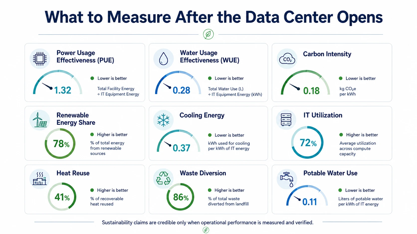
What Should Be Measured After Opening?
| Measure | Boundary / context | Owner, response, and closeout evidence |
|---|---|---|
| Energy + PUE | IT, cooling, electrical losses, total facility, interval, load, and weather | Energy manager: reconcile revenue-grade utilities and submeters monthly; investigate losses or control modes when the target is missed and retain corrected trend data |
| Water + WUE | Source, withdrawal, consumption, discharge, cooling mode, watershed, and IT denominator | Water-system operator: reconcile source meters and the water balance monthly; investigate leaks, cycles, or mode changes and retain drought-mode test logs |
| Carbon + clean energy | Declared operational or lifecycle boundary, grid location, time interval, and residuals | Sustainability lead: reconcile utility, fuel, contract, and energy-attribute records to the approved method; disclose or cure unmatched residuals |
| Resilience emissions | Generator tests and events, fuel, refrigerant charge, additions, recovery, and leakage | Facility manager: review run, fuel, service, and refrigerant inventory records after tests, events, and service; investigate abnormal consumption or leakage |
| Heat + materials + waste | Useful exported heat, upgrading energy, construction and operating waste, electronics, and destinations | Asset and waste owners: reconcile thermal meters to customer records and manifests to take-back or destination evidence; reject unsupported recovery claims |
| Commissioning + controls | Seasonal, part-load, maintenance, failure, and redundancy modes | Commissioning and operations leads: review trends, open issues, assign corrective actions, retest failures, and retain continuous-commissioning reports |
THE SEVEN-STEP DEVELOPER DEPLOYMENT PATH
Unlike the technical 10 Steps to Move a Data Center Toward Net Zero roadmap, this developer deployment path explains how a developer carries the sustainability strategy from feasibility through operation.
- Step 1
— Define the Sustainability Target Before Underwriting
Define exactly what the project is pursuing: LEED (Leadership in Energy and Environmental Design) Platinum, Net-Zero Energy, Net-Zero Carbon, 24/7 carbon-free energy, or a combination. Establish the accounting boundary, certification pathway, verification method, budget allowance, and accountable owner before the sustainability claim enters underwriting.
- Step 2
— Screen the Site Before Committing the Land
Test power availability and phasing, water availability and watershed stress, cooling feasibility, climate, flood and grading exposure, habitat and wetlands, renewable-energy access, acoustics, sensitive neighbors, transmission requirements, and future campus expansion before acquisition.
- Step 3
— Build One Integrated Energy-Water-Carbon Model
Use one coordinated IT (Information Technology) load profile, weather basis, operating assumptions, redundancy basis, and phasing assumptions across PUE (Power Usage Effectiveness), WUE (Water Usage Effectiveness), cooling, operational carbon, renewable procurement, and lifecycle analysis.
- Step 4
— Lock Performance Requirements Into Design
Convert sustainability objectives into measurable design criteria including electrical losses, cooling performance, water budgets, refrigerant requirements, embodied-carbon limits, metering boundaries, commissioning requirements, acoustic criteria, site/ecology requirements, and the live LEED scorecard.
- Step 5
— Protect the Targets Through Procurement and Construction
Carry performance requirements into procurement and construction documents. Require relevant performance data, EPDs (Environmental Product Declarations), equipment efficiencies, refrigerant information, material quantities, control sequences, testing requirements, and substitution review. Do not accept value-engineering changes solely because they reduce first cost if they materially compromise the approved energy, water, carbon, resilience, or certification strategy.
- Step 6
— Commission and Prove the Systems Before Handover
Commission equipment, controls, meters, cooling modes, redundancy sequences, storage dispatch, water systems, alarms, and failure modes. Resolve deficiencies and reconcile installed systems and quantities against the approved sustainability and certification basis before handover.
- Step 7
— Measure, Verify, and Correct Actual Performance
After opening, reconcile utility meters, submeters, generator fuel, refrigerant records, renewable-energy attributes, storage losses, water consumption, exported heat, and operating conditions. Compare actual operation against approved targets, investigate misses, implement corrective action, and support public sustainability claims only with reconciled evidence.
FEASIBILITY → TARGET → INTEGRATED MODEL → DESIGN REQUIREMENTS → PROCUREMENT CONTROL → COMMISSIONING → VERIFIED OPERATION
How DCFR Would Evaluate Sustainable and Net-Zero Data Center Feasibility
Resolve thirteen connected decisions with a declared boundary, accountable owner, evidence, failure signal, and confirmation date before major capital is committed.
13 Developer Sustainability Decision Gates
- Workload + IT demand — Confirm useful compute, utilization, growth, rack density, and flexibility from a documented workload and IT-energy basis.
- Facility energy — Model total and peak load across climate, load, maintenance, and failure conditions rather than a single design point.
- Electrical efficiency — Confirm UPS, transformer, distribution, harmonics, controls, and part-load losses without weakening protection or resilience.
- Cooling — Compare the complete heat path through hourly energy, water, climate, reliability, land, noise, and maintenance analysis.
- Water + watershed — Confirm sources, peak capacity, quality, drought durability, treatment, discharge, WUE boundary, and local scarcity.
- Clean-energy supply + carbon — Define the claim boundary and test contracts, attributes, location, timing, deliverability, additionality, and residual emissions.
- Backup power + refrigerants — Preserve required resilience while accounting for fuel, tests, emergencies, refrigerant GWP, leakage, and lifecycle responsibility.
- Embodied carbon — Identify dominant systems through project LCA, quantities, comparable EPDs, procurement controls, and substitution tracking.
- Heat reuse — Confirm customer, temperature, distance, simultaneous demand, upgrading energy, ownership, agreement, and net useful delivery.
- Land + ecology + community — Test surveys, stormwater, acoustics, traffic, water and grid effects, engagement, resilience, and cumulative impacts.
- Circularity + waste — Establish prevention, reuse, take-back, qualified recovery, data security, and destination evidence.
- LEED + certification pathway — Confirm current rating system, boundary, prerequisites, point strategy, Platinum-specific requirements, owners, and evidence.
- Measurement + verification — Fund meter architecture, commissioning, data quality, operating ownership, reporting, and claim review.
Reduce first. Decarbonize second. Verify everything.
DCFR Sustainability Decision Flow
- Workload
- Facility energy
- Electrical
- Cooling
- Water
- Clean energy + carbon
- Backup + refrigerants
- Embodied carbon
- Heat reuse
- Land + community
- Circularity
- LEED pathway
- Verification
Sustainability Failure / Risk Signals
- Undefined Net-Zero boundary
- PUE treated as the only metric
- Liquid cooling called water-free
- Annual matching called 24/7 carbon-free operation
- Unconfirmed water or renewable supply
- Heat reuse without a customer
- LCA excludes major infrastructure
- Backup power or refrigerants omitted
- LEED Platinum equated with Net Zero
- Certification begins after procurement
- No operational verification
Current Technical Basis — August 2026
U.S. Green Building Council
LEED v5U.S. Green Building Council
LEED v5 BD+C: New Construction and Major Renovations credit libraryU.S. Green Building Council
LEED rating system scorecards and certification levelsU.S. Green Building Council
Applying LEED to data center projectsU.S. Green Building Council
LEED ZeroU.S. Green Building Council
LEED addenda databaseU.S. Department of Energy
Best Practices Guide for Energy-Efficient Data Center DesignASHRAE, NEMA, and Pacific Northwest National Laboratory · 2026
AI Data Center Energy Performance FrameworkTechnical basis reviewed August 2026. Cooling technology, equipment capability, vendor qualification, and industry guidance continue to evolve; project decisions should use the latest applicable manufacturer data and professional engineering analysis.
Capacity-delivery review checklist
What to verify before the next release gate.
- DEVELOPER — Confirm power, water, watershed, climate, renewable procurement, land, ecology, community, schedule, and expansion before acquisition.
- DEVELOPER + SUSTAINABILITY CONSULTANT — Define the certification pathway, Net-Zero boundary, accounting period, evidence, budget, and accountable owners before underwriting release.
- ARCHITECT + CIVIL ENGINEER — Coordinate land efficiency, habitat, stormwater, grading, heat island, lighting, acoustics, traffic, and resilient expansion.
- MEP ENGINEERS — Model electrical and cooling alternatives across hourly climate, load, maintenance, drought, and failure conditions, including PUE and WUE boundaries.
- ARCHITECT + STRUCTURAL ENGINEER + CONTRACTOR — Maintain the LCA, material quantities, EPD basis, embodied-carbon targets, circularity requirements, and substitution register.
- DEVELOPER + ENERGY ADVISOR — Verify clean-energy contracts, attributes, location, timing, additionality, residual emissions, storage losses, and expansion treatment.
- SUSTAINABILITY CONSULTANT — Maintain current prerequisites, credits, Platinum-specific requirements, scorecard contingency, documentation, addenda, and review comments.
- CONTRACTOR + COMMISSIONING TEAM — Protect meters, controls, equipment performance, water, refrigerants, materials, testing, findings, and corrective actions through delivery.
- OWNER / OPERATOR — Own interval data, utility reconciliation, controls, maintenance, continuous commissioning, public claims, and corrective action after opening.
What DCFR would flag
Delivery risks that should be visible early.
DCFR would flag unsupported claims; missing energy, carbon, water, watershed, refrigerant, embodied-carbon, or lifecycle boundaries; unverified renewable attributes or heat customers; and any conclusion lacking required utility, engineering, AHJ, GBCI, commissioning, certification, or operational confirmation.
Professional confirmation required
Items requiring project-specific validation.
Final conclusions require project-specific architectural, mechanical, electrical, civil, structural, environmental, acoustic, utility, water, commissioning, certification, and operational analysis; current code and AHJ coordination; vendor data; owner requirements; and formal certification review. This guidance is not a utility commitment, engineering design, certification determination, or guarantee of Net-Zero performance.
Final takeaway
SITE IT RIGHT. REDUCE DEMAND. DESIGN THE SYSTEM AS A WHOLE. PROTECT THE TARGETS THROUGH PROCUREMENT. COMMISSION IT. MEASURE IT. VERIFY THE CLAIM.
Surface site, code, utility, and delivery risk before it becomes expensive.
DCFR converts early assumptions into planning-grade flags, confirmation registers, and decision-ready feasibility outputs.