
DCFR Insight 103 / Architecture & Resilience
Climate-Responsive Envelope Variants
How to preserve one global data-center platform while changing the wall and roof physics that each climate demands.
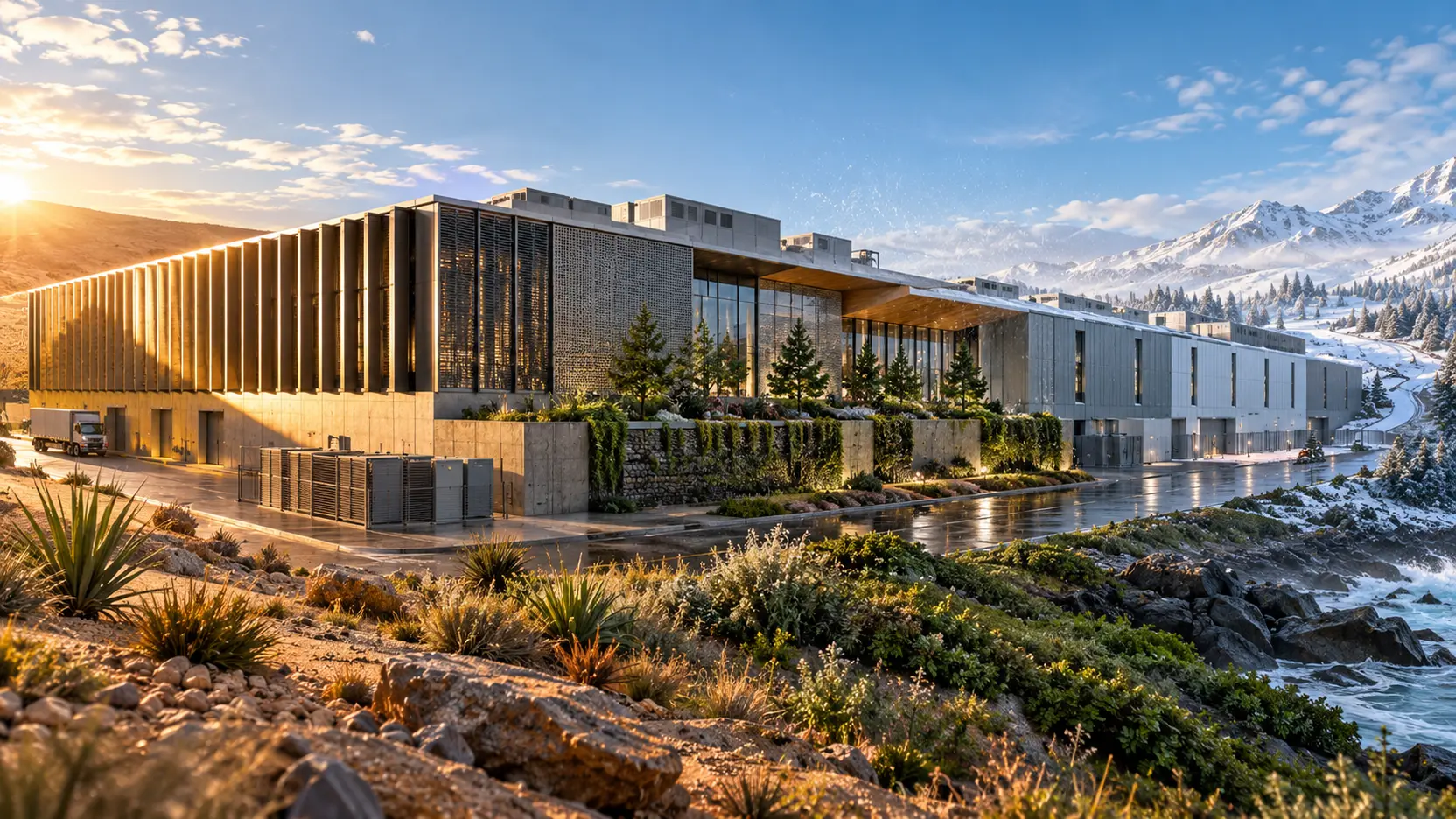
One Platform Does Not Mean One Assembly
A global data-center reference design should standardize performance, interfaces, and evidence—not force the same wall and roof assembly into climates with fundamentally different heat, moisture, wind, dust, salt, snow, and fire conditions.
The attraction of one repeated envelope is real: familiar panel dimensions, stable suppliers, common details, faster reviews, and comparable inspection records. But visual repetition can conceal physical mismatch. A hot-humid coastal wall may experience warm moisture driven inward toward a cold data hall. A subarctic wall sees the opposite vapor drive, severe thermal bridges, snow accumulation, and brittle low-temperature seals. Hot-arid sites add solar load, dust, rare intense rain, and large daily movement. Mixed climates reverse vapor direction seasonally.
The scalable product is therefore a controlled envelope platform with bounded, evidence-based variants. The program preserves repeatable geometry, interfaces, testing, and governance while allowing each location to change the layer position, capacity, material class, exposure resistance, and maintenance regime required by its actual climate.
Standardize Five Continuous Control Functions
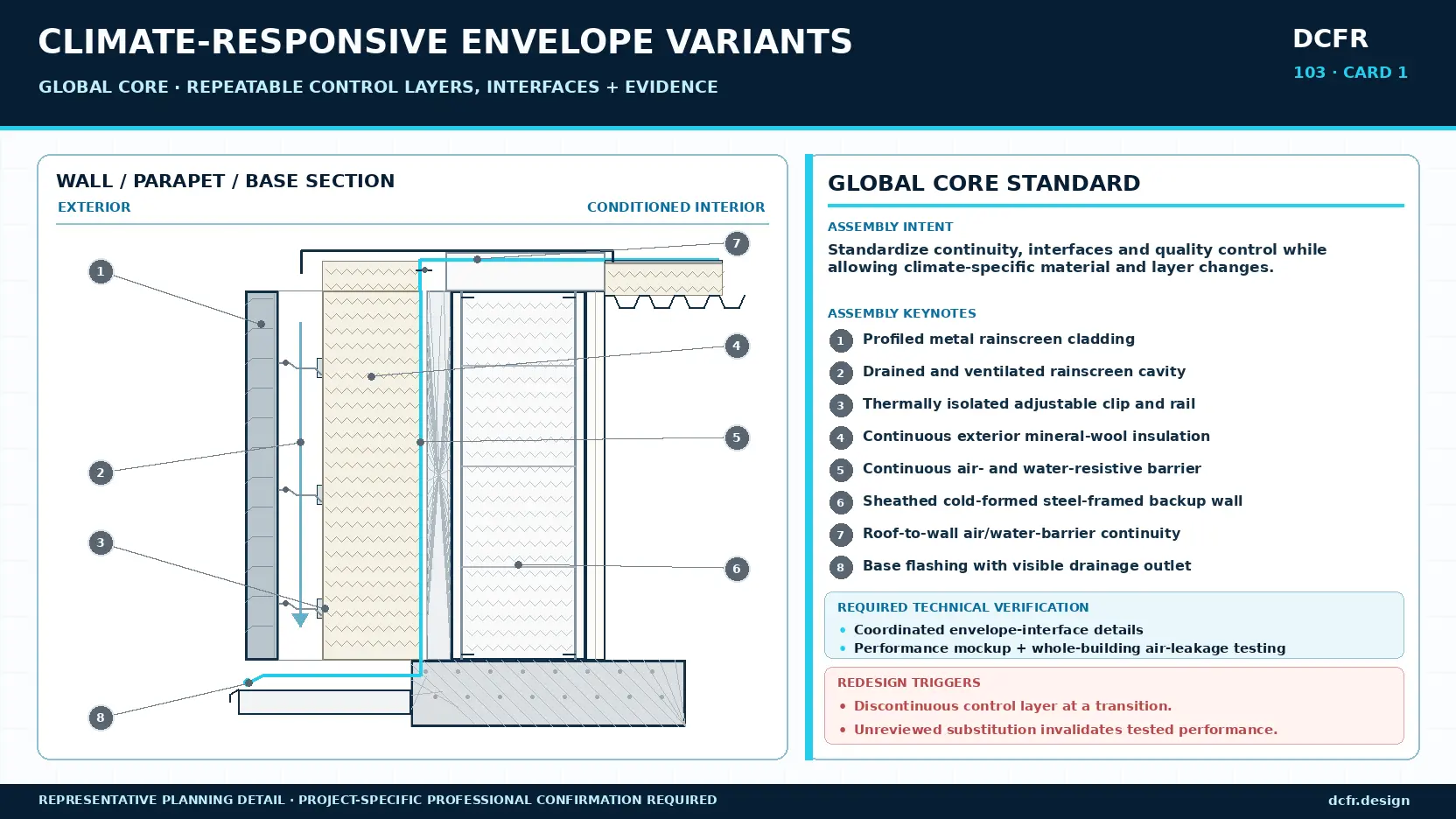
Every wall and roof must maintain continuous rainwater, air, thermal, vapor, and fire-control functions. These functions—not a single material stack—form the global core.
Rainwater control sheds bulk water, collects what passes the outer skin, drains it safely, and retains a drying path. Air control creates a continuous, testable pressure boundary around conditioned and critical spaces. Thermal control provides continuous insulation and limits bridges at structure, fasteners, openings, and transitions. Vapor control manages diffusion and condensation according to climate, indoor conditions, permeance, and drying potential. Fire control preserves the tested strategy across panels, joints, cavities, penetrations, and roof-wall transitions.
The reference platform should fix the structural and panel module, primary air-barrier interface, drainage logic, penetration philosophy, movement strategy, tolerances, inspection access, test format, and change process. The variant should define insulation, vapor-control position, cavity ventilation, finish and coating class, fasteners, sealant temperature range, roof and snow provisions, opening protection, corrosion resistance, and inspection frequency.
Establish the Climatic and Environmental Basis of Design
An ASHRAE climate-zone label is a starting point, not an envelope design basis. Release-quality decisions require coincident environmental conditions, local exposure, indoor operating states, and future stress cases.
The climate memorandum should include heating and cooling design temperatures; coincident dry-bulb, humidity, and dew point; annual and seasonal rain; wind direction, speed, and rain coincidence; solar radiation and orientation; snow, ice, freeze-thaw, and roof drainage; airborne salt, sand, smoke, and industrial contaminants; flood or splash exposure; wildfire or ember risk; and projected changes over the service life.
Record the source station, elevation difference, period of record, missing variables, microclimate adjustments, future scenario, owner risk tolerance, and the exact design decision controlled by each value. Two sites sharing a climate zone may still have materially different solar, wind-driven-rain, salt, snow, and wildfire exposures.
Hot-Arid Variant: Solar, Dust, and Movement
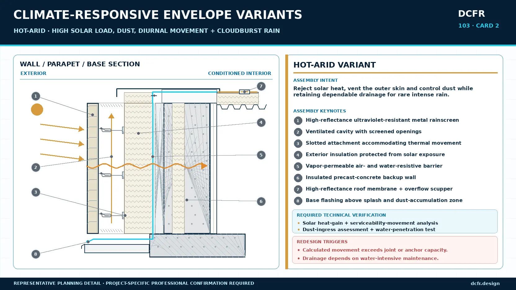
Hot-arid envelopes must reduce absorbed heat, tolerate wide surface-temperature swings, resist dust intrusion, and remain ready for infrequent but intense rainfall. Low annual rainfall does not mean low leakage consequence.
Use high-reflectance, ultraviolet-resistant finishes; exterior shading or deep reveals; pressure-moderated cavities where appropriate; high-temperature-rated gaskets and sealants; anchors and joints designed for calculated serviceability movement; dust-resistant louvers, doors, and penetrations; and drainage paths that remain functional after dust accumulation. Cleaning and inspection procedures should not depend on abundant water.
Required verification should include solar heat-gain and exterior surface-temperature analysis, cyclic displacement testing, ultraviolet and gasket aging, dust-ingress assessment, louver pressure-drop and filtration analysis, and water-penetration testing after movement conditioning. Redesign is required if obstructed drainage, sealant degradation, or calculated thermal movement can compromise the primary drainage plane before the next scheduled inspection.
Hot-Humid and Coastal Variant: Inward Moisture and Corrosion
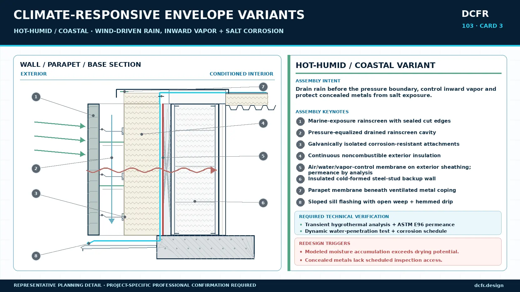
Where exterior air is warmer and wetter than the conditioned interior, leakage and vapor drive can carry moisture inward toward cold surfaces. Added insulation changes temperature profiles and drying behavior, so the assembly must be analyzed as a system.
Priorities include a drained and ventilated rainscreen; continuous exterior air and water control; vapor-control placement based on interior setpoints and hygrothermal analysis; thermally isolated interior surfaces; two-stage joints; enhanced flashing at ledges, louvers, doors, and roof edges; and corrosion-resistant cladding, rails, anchors, fasteners, and accessories.
The reference detail should identify a product category and measurable performance rather than a proprietary brand. For example: a fully adhered air-, water-, and vapor-control membrane with vapor permeance selected by transient hygrothermal analysis; material air permeance and assembly air-leakage performance verified under the applicable ASTM methods; demonstrated adhesion to the actual substrate; compatible primers, flashings, sealants, and transition membranes; and installation-temperature, ultraviolet-exposure, and fire-performance limits coordinated with the complete wall assembly. Named basis-of-design products should be introduced only in the project specification after system compatibility and tested-assembly evidence have been reviewed.
Coastal exposure is more than humidity plus stainless steel. Salt attacks cut edges, concealed fasteners, subframes, coils, and rooftop equipment. One corrosion matrix should coordinate coating systems, alloys, isolation washers, edge treatment, wash-down, inspection access, and replacement cycles. The assembly requires redesign if analysis predicts persistent condensation, the wall has no credible drying direction, or concealed-metal life is shorter than the inspection interval.
Cold and Mixed Variants: Continuity, Reversal, and Cycling
Cold climates demand continuous exterior insulation, controlled interior moisture, low-temperature materials, and deliberate snow and ice management. Mixed climates add seasonal reversal and frequent wetting, drying, heating, and cooling cycles.
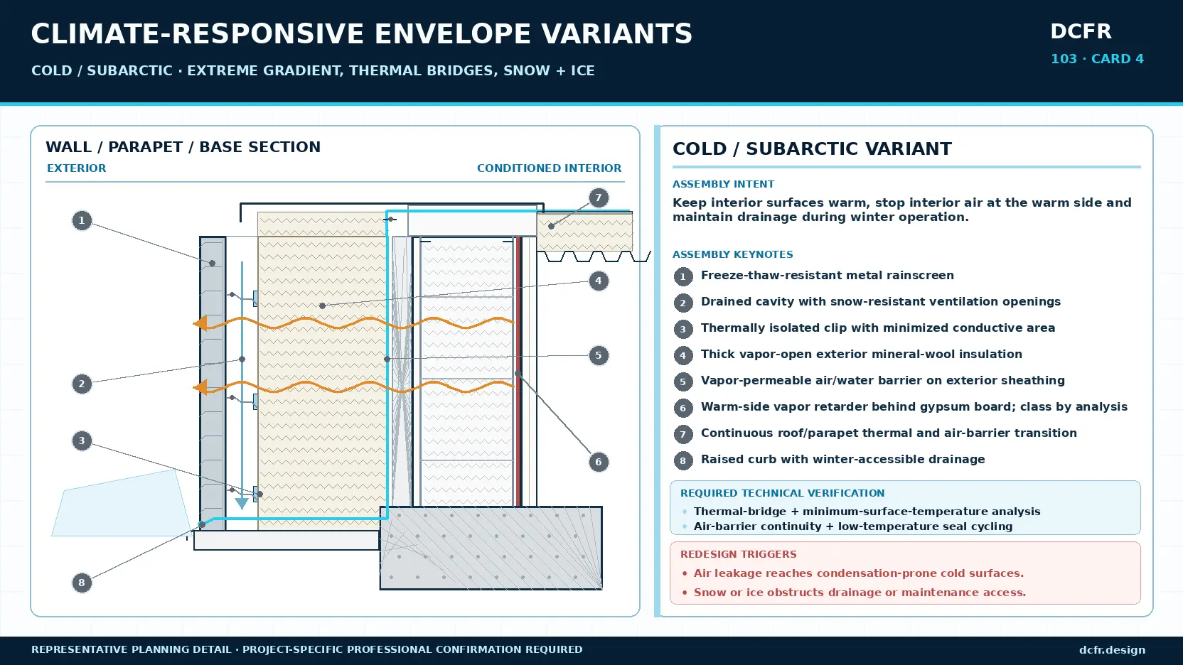
For cold and subarctic sites, maintain continuous insulation across columns, girts, parapets, openings, and attachment systems; thermally isolate subframing; locate air- and vapor-control layers for the project-specific interior design conditions; qualify sealants and membranes for installation and service temperatures; and coordinate roof edges, overflow drainage, snow drifting, heat tracing, drainage, and safe winter access. Three-dimensional heat-flow analysis should quantify linear and point thermal bridges at panel joints, doors, primary structure, wall bases, and roof-to-wall transitions rather than relying on nominal insulation values.
The reference cold-climate section uses a product-neutral rainscreen wall: exterior cladding, a drained and ventilated cavity, thermally isolated attachments, thick vapor-open continuous mineral-wool insulation, a vapor-permeable air- and water-resistive barrier on exterior gypsum sheathing, an insulated cold-formed steel-stud backup wall, and interior gypsum board. Where a warm-side vapor retarder is required, it is located immediately behind the interior gypsum board—not adhered to a metal panel—and its vapor-retarder class is selected from the governing climate-zone requirements and project-specific hygrothermal analysis.
DOE/PNNL identifies two valid cold-climate approaches: a Class I or II vapor retarder at the interior with an outward drying path, or a more vapor-open Class III interior finish where sufficient exterior continuous insulation keeps the sheathing warm. The published detail therefore identifies the control-layer location without prescribing a proprietary membrane. Final permeance, exterior-to-cavity insulation ratio, and drying direction must be documented for the actual climate zone, indoor design humidity, and service conditions.
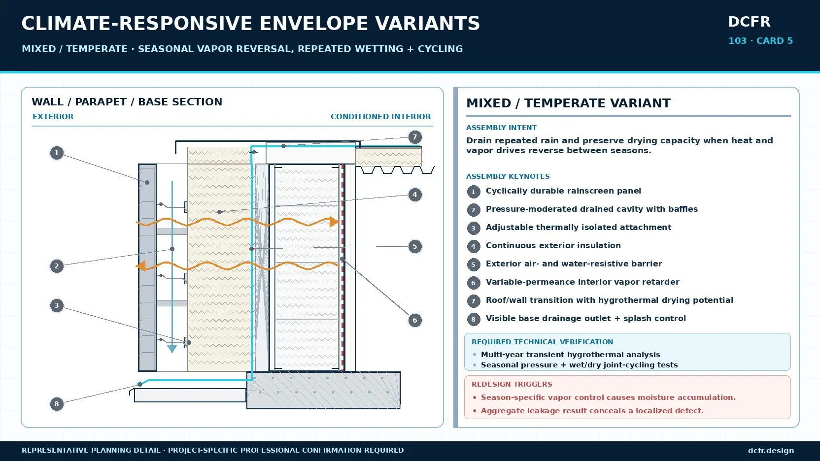
For mixed and temperate sites, use assemblies with demonstrated bidirectional drying potential where feasible, vapor-control layers selected through transient hygrothermal analysis, drained and pressure-moderated cavities, and joints qualified for repeated environmental cycling. Verify both heating- and cooling-dominant differential-pressure regimes. A one-direction vapor-control strategy is not acceptable without analysis of seasonal vapor-drive reversal.
Climate-Responsive Variant Matrix
| Climate variant | Principal exposure | Envelope design response | Required verification |
|---|---|---|---|
| Hot-arid | Solar radiation, dust, thermal movement, infrequent high-intensity rainfall | High-reflectance finishes, movement joints, dust-resistant openings, maintainable drainage | Thermal cycling, ultraviolet aging, dust-ingress assessment, and water-penetration testing after movement conditioning |
| Hot-humid / coastal | Inward moisture drive, wind-driven rain, salt corrosion | Drained rainscreen, exterior control layers, corrosion matrix, two-stage joints | Hygrothermal margin, dynamic water, material and concealed-fastener life |
| Cold / subarctic | Extreme temperature gradient, snow, ice, freeze-thaw cycling, low-temperature material behavior | Continuous insulation, warm-side air/vapor control, low-temperature-rated materials, snow and ice detailing | Three-dimensional heat-flow analysis of linear and point thermal bridges, minimum interior surface temperature, low-temperature movement, and drainage verification |
| Mixed / temperate | Seasonal vapor-drive reversal, repeated wetting/drying and freeze-thaw cycling | Bidirectional drying potential, analysis-based vapor permeance, drained cavity, and cyclically qualified joints | Multi-year transient hygrothermal analysis and testing under heating- and cooling-dominant differential-pressure regimes |
Define Controlled Hazard-Specific Design Modifiers
Climate is the base layer. Hurricane, wildfire, corrosion, dust, flood, and hail exposures should modify the eligible variant through controlled overlays rather than create an unmanaged global catalog.
Hurricane and typhoon overlays raise pressure, cyclic loading, wind-driven-rain, impact, roof-edge, and opening requirements. Wildfire overlays add ember-resistant openings, noncombustible exterior zones, smoke-mode pressure control, replaceable filters, and post-event cleaning. Dust overlays change louvers, vestibules, filters, service penetrations, and collection zones. Flood overlays raise openings, protect drainage exits, and introduce sacrificial or washable lower-wall materials. Hail overlays require impact resistance and post-event inspection.
Each hazard-specific design modifier should identify compatible base variants, revised details, affected calculations and tests, incompatible combinations, and approval responsibility. The objective is controlled variation sufficient to address project exposure without creating an unverified one-off assembly.
Most Failures Occur at Interfaces
The center of a factory panel is rarely the hardest condition. Risk concentrates where a control layer turns, changes material, crosses a trade boundary, or becomes concealed.
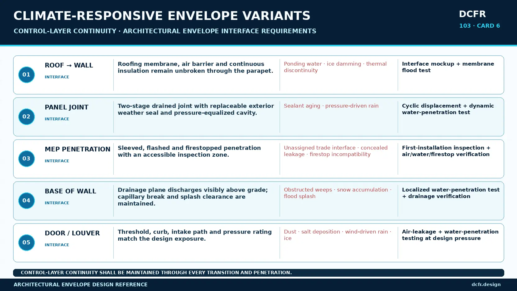
At the roof-to-wall transition, roofing membrane, air barrier, thermal insulation, fire-resistance provisions, and drainage must remain continuous through a constructible parapet sequence. Panel joints require a protected inner air-and-water seal, an exterior weather seal, and a drained or pressure-equalized cavity where appropriate. MEP penetrations require standardized sleeves, curbs, flashing, firestopping, dimensional tolerances, and an assigned responsible party; field-applied sealant spanning multiple trades is not an acceptable interface-control strategy.
At the wall base, drainage should discharge visibly above grade and remain clear of paving, landscaping, snow, and splash. Doors and louvers must match the surrounding wall's pressure, water, dust, salt, and ice performance. Each interface should have a stable ID linking geometry, materials, tolerances, test evidence, inspection photographs, repair method, and change history.
Validate the Production System
A climate variant is not ready because its analysis is credible. It is ready when the intended supplier, factory process, field sequence, tolerances, interfaces, and tests reproduce the required performance.
Begin with review of the climatic basis of design, whole-assembly thermal-transmittance calculations, three-dimensional heat-flow analysis of linear and point thermal bridges, multi-year transient hygrothermal analysis, structural and serviceability-movement calculations, and material-compatibility review. Then test a laboratory performance mockup for air leakage, static and dynamic water penetration, structural wind pressure, displacement accommodation, and repeat performance after environmental conditioning where appropriate.
Follow with first-article factory review, field performance mockup, installation quality-control audits, concealed-work inspections, and whole-building air-leakage testing that records both aggregate leakage and diagnostic leakage locations. Commissioning records should preserve infrared thermography, leakage-test results, measured moisture conditions, repairs, approved deviations, and inspection zones as the operational baseline.
Approve the Variant Only When Six Evidence Domains Converge
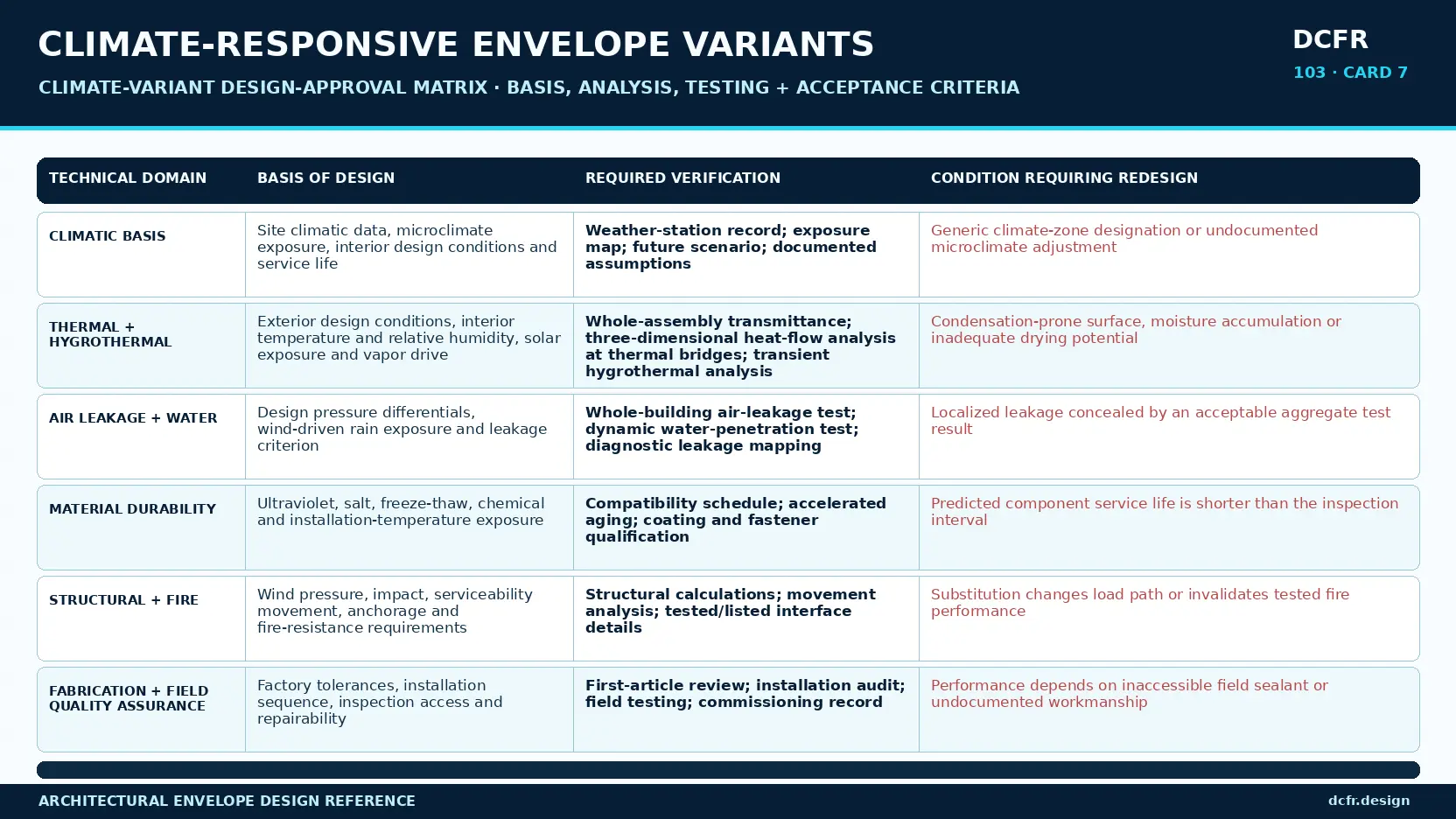
Design approval must address climatic basis of design, thermal and hygrothermal performance, air leakage and water penetration, material durability, structural and fire performance, and fabrication, installation, and commissioning. All six domains must describe the same controlled assembly and operating conditions.
Redesign is required when the climatic basis of design is incomplete; modeled moisture accumulation exceeds the assembly's drying potential; an acceptable aggregate air-leakage result conceals a critical localized defect; a concealed component's predicted service life is shorter than the inspection interval; a substitution invalidates structural or fire-performance evidence; or required performance depends on inaccessible field-applied sealant.
The design-approval package should identify the global core, applicable climate variant, hazard-specific design modifiers, site-specific adaptations, approved materials and manufacturers, critical interfaces, test pressures and acceptance criteria, inspection hold points, repair procedures, maintenance intervals, and the change-control process for every substitution.
Minimum Evidence for Climate-Variant Approval
| Technical domain | Minimum required evidence | Condition requiring redesign |
|---|---|---|
| Climatic basis of design | Site-specific climatic data, microclimate and hazard exposure, interior design conditions, future climate scenario, and design service life | Generic climate-zone designation or undocumented microclimate adjustment |
| Thermal + hygrothermal | Whole-assembly thermal transmittance; three-dimensional heat-flow analysis of linear and point thermal bridges; minimum interior surface temperature; transient moisture accumulation and drying potential | Persistent moisture accumulation, insufficient drying potential, or an unmodeled condensation-prone surface |
| Air leakage + water penetration | Design differential pressures, air-leakage performance criterion, diagnostic leakage mapping, dynamic water-penetration testing, and drainage verification | Localized air or water leakage concealed by an acceptable aggregate test result |
| Material durability + compatibility | Ultraviolet, salt, freeze-thaw, and chemical exposure; sealant installation/service temperatures; galvanic and substrate compatibility; replacement cycle | Predicted concealed-component service life shorter than the scheduled inspection interval |
| Structural + fire performance | Structural wind pressure, serviceability movement, impact resistance, anchorage, cavity fire barriers, firestopping, and tested transitions | Material substitution or construction tolerance invalidates the tested or engineered configuration |
| Fabrication, installation + commissioning | Factory quality control, installation sequence, inspection hold points, repairability, field testing, and commissioning record | Required performance depends on inaccessible field sealant or undocumented workmanship |
Five Innovations for a Learning Envelope Platform
The strongest innovations make climate response more measurable, maintainable, and reusable across the portfolio rather than adding novelty to the façade.
First, parametric eligibility rules can connect site weather, dew point, rain, salt, snow, wildfire, and indoor setpoints to the envelope families allowed to proceed. Second, control-layer interface passports can preserve detail geometry, materials, tolerances, fire evidence, tests, photos, installers, repair methods, and change history under one stable ID.
Third, exposed weather seals, gaskets, closures, and flashings can be designed as reachable replacement parts that do not disturb the primary air barrier. Fourth, sensing by exception can monitor a limited set of hidden, consequential interfaces against the commissioning baseline. Fifth, a portfolio defect-to-detail loop can normalize leaks, corrosion, thermal anomalies, and repairs by interface ID and variant so one site's lesson updates every related configuration.
Architectural Envelope Design-Review Criteria
Before design approval, the owner and design team should identify the climatic and hazard data governing the design, future conditions beyond minimum code requirements, and the continuous path of all five control functions at every transition.
The design team should distinguish the global core, climate variant, hazard-specific design modifier, and site-specific adaptation; document drainage and drying paths; identify conditions where air leakage could transport moisture to a condensation-prone surface; and document material exposure to ultraviolet radiation, salt deposition, dust, freeze-thaw cycling, cleaning chemicals, and installation temperature.
Finally, demonstrate the laboratory, mockup, factory, field, and whole-building evidence; prove that weathering components, drains, coatings, and sensors can be inspected and replaced without disrupting critical operations; and identify which evidence must be reopened when any supplier, coating, sealant, fastener, panel, insulation, or sequence changes. Without those answers, the project has an exterior appearance—not a climate-responsive envelope.
DCFR Design Principle
Global consistency should make climate response more disciplined, not less. The controlled product is a system of performance requirements, interfaces, tested details, bounded options, and evidence. The local expression is the assembly that manages the site's real heat, air, water, vapor, fire, and hazard conditions.
A repeatable platform can accelerate design and procurement only when variation is explicit and governed. Standardize interface requirements and performance verification. Adapt the assembly to project-specific heat, air, moisture, fire, and exposure conditions. Incorporate operating evidence into subsequent approved configurations.
Early screening checklist
What to verify before advancing this site.
- Record the site weather source, microclimate adjustments, indoor setpoints, hazards, future stress cases, and service life.
- Map rain, air, thermal, vapor, and fire-control continuity through every roof, wall, opening, base, and penetration detail.
- Separate the controlled global core from climate variants, hazard-specific design modifiers, and site-specific adaptations.
- Calculate whole-assembly thermal transmittance; perform three-dimensional heat-flow analysis of linear and point thermal bridges; and evaluate multi-year transient hygrothermal performance and seasonal differential-pressure regimes.
- Coordinate coatings, metals, fasteners, membranes, sealants, insulation, firestops, cleaners, and replacement cycles.
- Test laboratory mockups, first-article production, field installation, whole-building leakage, and localized defect conditions.
- Design exposed seals, flashings, drains, coatings, and sensors for safe inspection and replacement during live operation.
- Reopen affected analysis and test evidence whenever a material, supplier, tolerance, detail, or installation sequence changes.
What DCFR would flag
Risks surfaced at the screening stage.
DCFR would flag an envelope proposal that applies one assembly globally without a documented climatic basis of design, explicit control-layer continuity, climate-specific thermal and hygrothermal analysis, controlled hazard-specific design modifiers, full-scale performance testing, and configuration-controlled evidence for substitutions.
Professional confirmation required
Items requiring licensed validation.
Final design requires project-specific confirmation by the architect, envelope consultant, structural and fire engineers, mechanical designer, manufacturer, commissioning authority, owner, insurer where applicable, and Authorities Having Jurisdiction. Climate data, indoor setpoints, vapor-control strategy, fire classification, structural loads, corrosion classes, material compatibility, and test pressures must be verified for the selected site and system.
Final takeaway
ONE GLOBAL PLATFORM SHOULD STANDARDIZE THE CONTROL LOGIC—NOT FORCE THE SAME ENVELOPE PHYSICS INTO EVERY CLIMATE.
Screen up to 20 candidate sites before selecting one for the full DCFR report.
Each DCFR Report Package includes a preliminary 20-site comparison PDF / export package plus one selected planning-grade feasibility report.